The Ultimate Motor Swap
DISCLAIMER: These articles and procedures are examples of how and what can be done. These all assume the use of proper tools and the M535i SIG and I take no reponsiblity for any incorrect information posted on this page. If you are not comfortable in undertaking any automotive repair, take your car to a qualified BMW mechanic. Otherwise use this information at your own risk. Like the copyright says any duplication of this information with out the explicit permission of the M535i Special Interest Group & Registry is prohibited. If you run into any specific problems please email me through the link at the bottom of the page and I will try to assist you as best I can.
WE DO NOT TAKE RESPONSIBILITY FOR ANYONE WHO WILL BE DOING THE MODIFICATIONS DESCRIBED BELOW. This is merely a guide and pictorial description of what we did during our swap. We had the benefit of a full ETM, ETK, and a well stocked shop, and other assistance. Anyone who uses this guide does so on their own responsibility, at their own risk, and with no implied guarantee on our part or liability. The information included here should be enough for a person with adequate mechanical knowledge to be able to use in support of their own resources, not as a primary resource.
INDEX
1. History and reasoning for swap
2. Purchase of motor
3. Refresh of motor
A. Receiving and InspectionB. Disassembly and checkingC. Refreshing components and parts4. Installation
A. Removal of old motor and engine bay preparationi. Heat shield from E28 M5ii. Battery and rewiringiii. B38 coolant pipesiv. Removal of engine bay brackets to clear intakev. Heater valve bracket adjustmentB. Engine InstallationC. Other Considerationsi. Expansion tank and other coolant system changes needed to interface to E28 chassisii. PS hoses and clearance to reservoir tank, adjustmentiii. Removal of airpump and AC systemiv. 140 amp alternatorv. Oil cooler linesD. Wiring considerationsi. Removal of air pumpii. Wiring loom - removal of superfluous wiringiii. X20 to C101 plug connectionsiv. Diagnostic plug wiring (same except needs power)v. AC wiring5. Final Productvi. C103 connector
1. History and reasoning for swap
The S38 B38 was BMW’s ultimate evolution of their traditional ‘big-six’ motor. It was the largest stock offering, with the latest head design, and most ‘hot rodding’ done to it. Our goal, our theory, for this build was to install this motor into an E28 “as BMW would have done it from the factory.” What does this mean? It means using as many stock components as possible and making all of the features and options work between the E28 and S38 B38.
There are a multitude of other options available. People can simply buy a stock S38 B35 and install it in the E28 – like the US M5. Or an M88/3. Or an S38B36 from the E34. And even if you go with a S38 B35, you can get it tricked out by just about anyone who knows a thing or two about BMW motors (e.g. Korman). You might have the same or more power than a stock B38, but we wanted to go with a car that looks as stock as possible – and that means no custom fabrication – or as little as possible.
Again, if we wanted the most power, we probably could have gone with the ultimate Dinan motor, their 3.9 liter powerhouse. But it wouldn’t have been consistent with our goal, and it’d have been far more expensive. Now, before we begin, we should discuss costs.
The one really enticing option is to start with a S38 B35, and hot-rod it with a full rebuild. If we outsource that, it’d probably be between $12,000-$14,000 (you can ask Korman how much their rebuilds go for). But taking that example, a Korman Stage 2 rebuilt 3.6 liter would be around $15,000, give or take, and give you 373 bhp according to their website. Add to that about $3,000 for the core motor, and then another $4,000 to $6,000 to install the motor into an E28 (e.g. coolant system, A/C, exhaust, etc), and you’re talking about something well north of $20,000. But, you do get a 2 year warranty from Korman – which is a good piece of mind.
So how much is an S38 B38? A good one with under 100k miles is probably $6,000, plus shipping from Europe. You’re talking $7,000 just to get the motor. Then there’s about $3,000 to refresh the long-block (timing chain components, new rod end bearings, intake rebuild – but no rebuild of the head or head gasket), and then approximately something north of $7,000 to install it (e.g. coolant system, A/C, exhaust, wiring, engine mounts, etc). So a ‘good’ S38 B38 installation starts around $17,000 in terms of cost. But what about a S38 B38 that’s questionable? You might be able to get one for $4,000 after shipping, but you’ll need to spend at least $12,000 to do a ‘stock rebuild’ and the same $7,000 for installation – so you’re still looking at a total cost north of $20,000.
These are all estimates – your costs may vary depending on what you decide to keep as is, replace, or rebuild. But we’re assuming that you’re going to want to replace as many components as possible to ensure reliable performance. As low-mileage S38 B38s become less available, it might be a necessity to get one and rebuild it. But suffice it to say, any way you look at it, it won’t be inexpensive.
When purchasing an S38 B38 there are a few things that you want to keep in mind. First off you want to learn as much about this motor as you can before you buy one. There are certain items on this motor which are not the most reliable and they are not easy to find. First item that must be considered is the condition and mileage of these motors. The 3.8L has a bad habit of destroying connecting rod big end bearings. These usually need to be replaced every 60k miles. Also the condition of the cooling system is very important. These motors can and do overheat the number 1 and number 6 cylinders.
2. Purchase of Motor
Here is a short list of items that will need to purchased with the motor. Obviously you want to get a complete long block. But the following items from the 3.8L need to be purchased with the motor. You will need to have the harmonic damper and accessory pulleys. You will need to have the intake and throttle bodies and the associated equipment. You will also need to have the MAF and the wiring harness with DME and you can purchase the alternator. You will need the coolant tubes with the motor along with the thermostat housing.
Now onto the non-3.8L parts that will be needed. You need to have E28/E24 M5/M6 engine mounting arms. You need an M30/M88/(E28/E24 S38) oil pan and oil pump. You need the accessory brackets from an M30/M88/(E28/E24 S38). You need an M88/S38 oil filter canister and mouting block. You will need an E28 M5 coolant overflow tank and an E28 535i radiator. The details of the hoses and other items will come later. Lastly you will need to purchase some adaptors (Koala motorsports) for the engine mounting brackets.
3. Refresh of motor
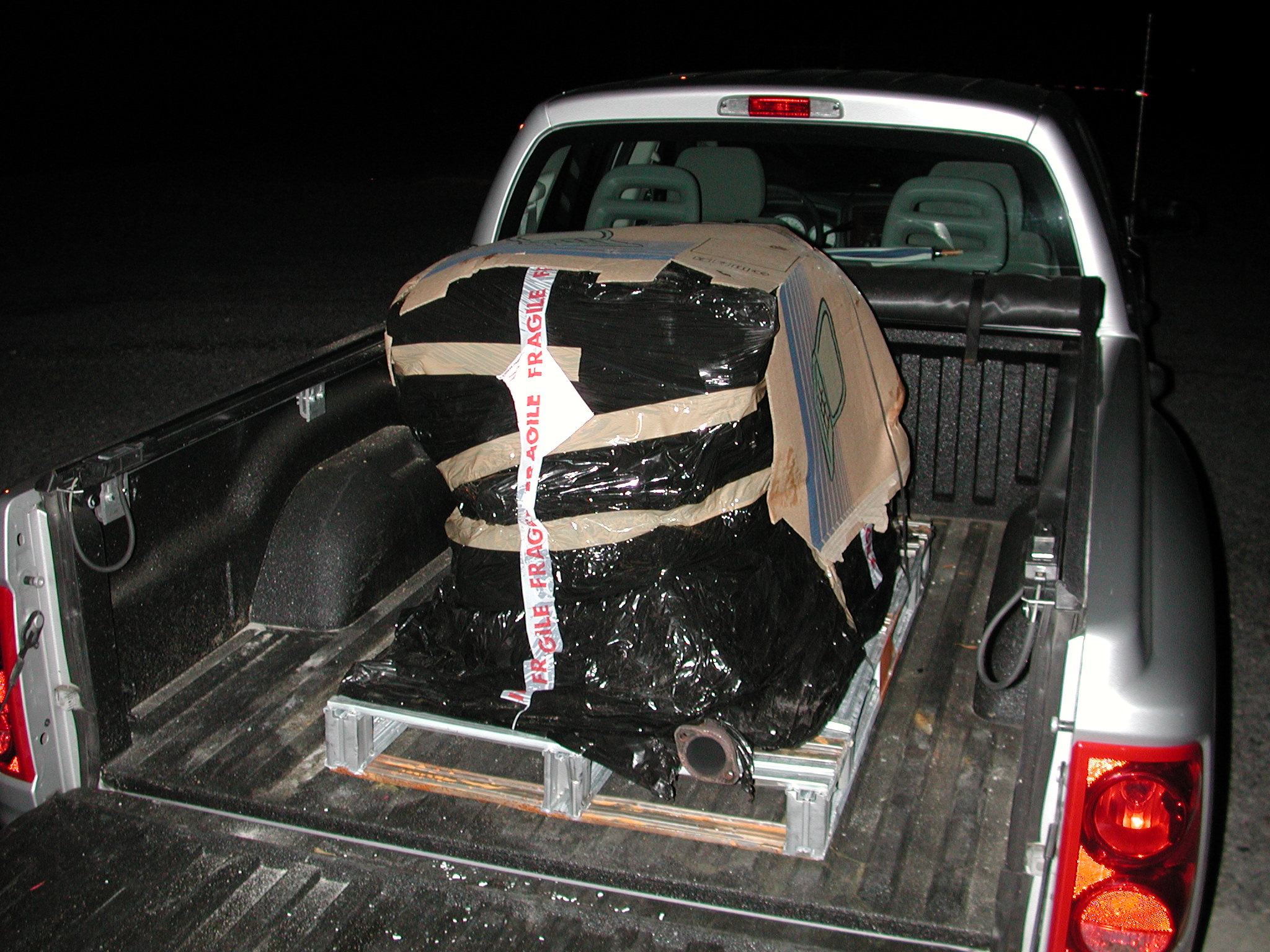
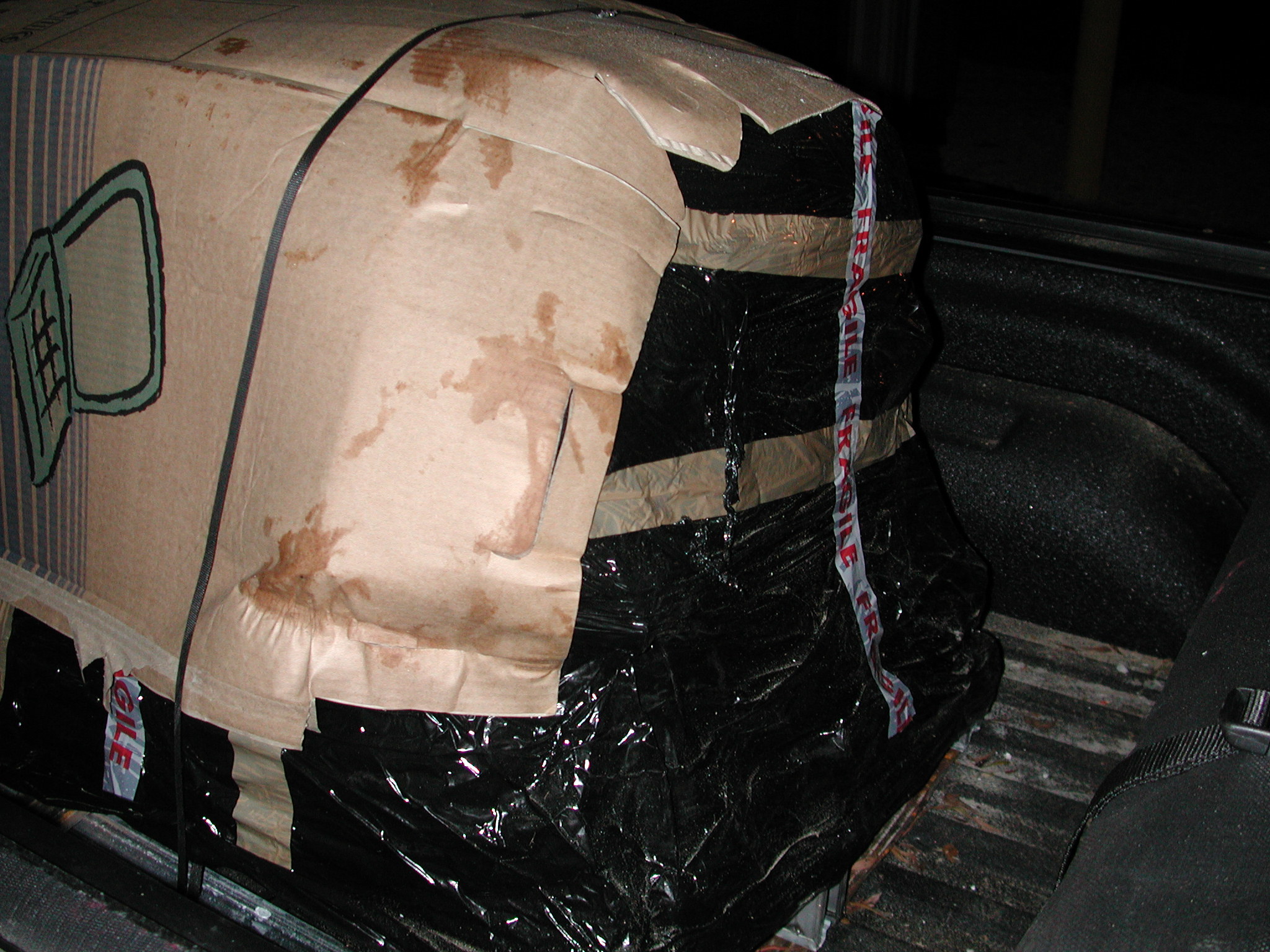
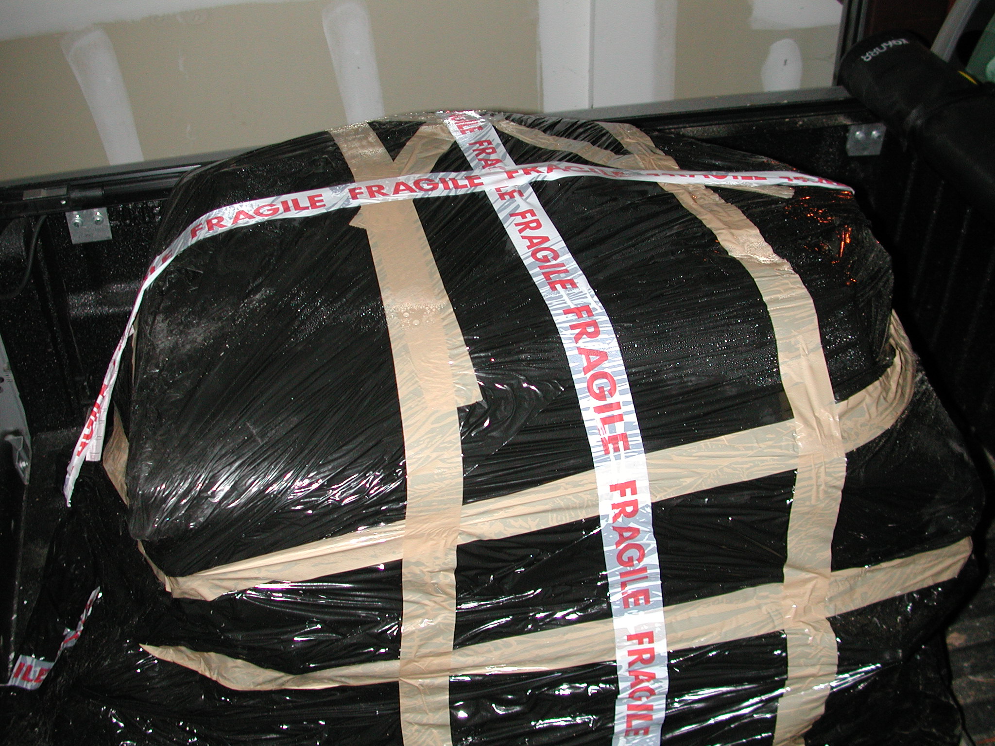
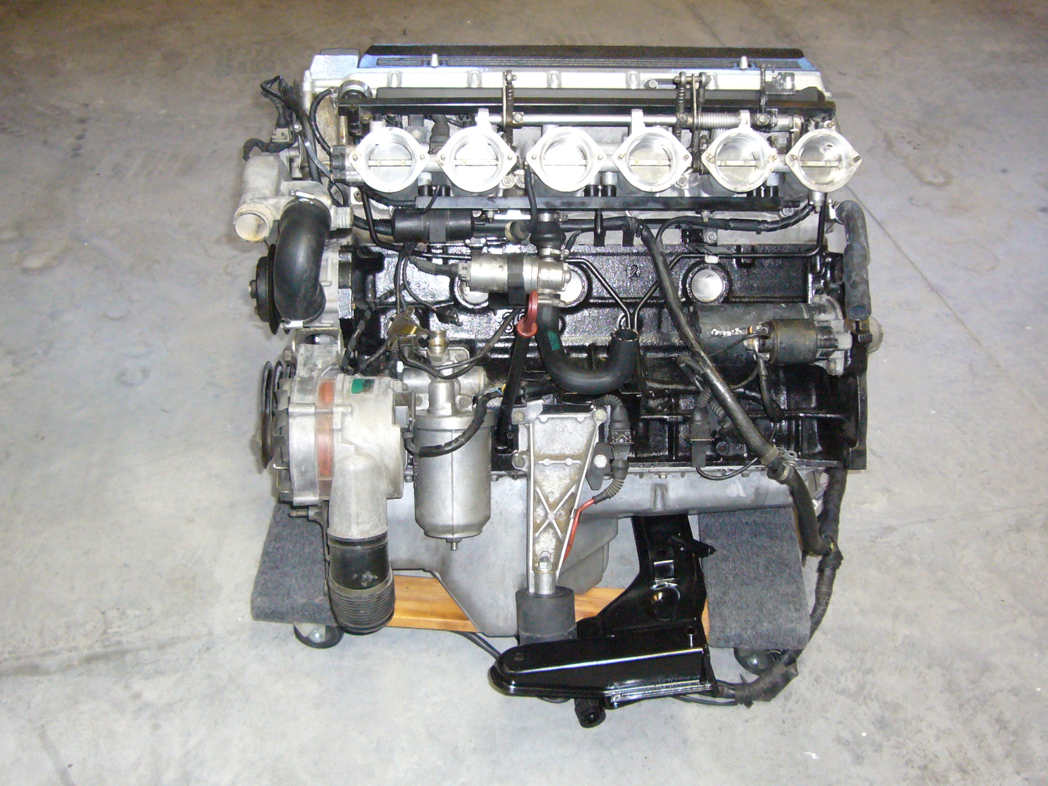
A. Receiving and InspectionIn this section we will discuss the items that need to be addressed in a typical refresh. We will also discuss some of the changes that will be made and some of the touches we put on this motor. To start with, when you take delivery of your motor you want to inspect it for damaged parts from shipping snd probably do a leak down test to ensure the motor is in good health.
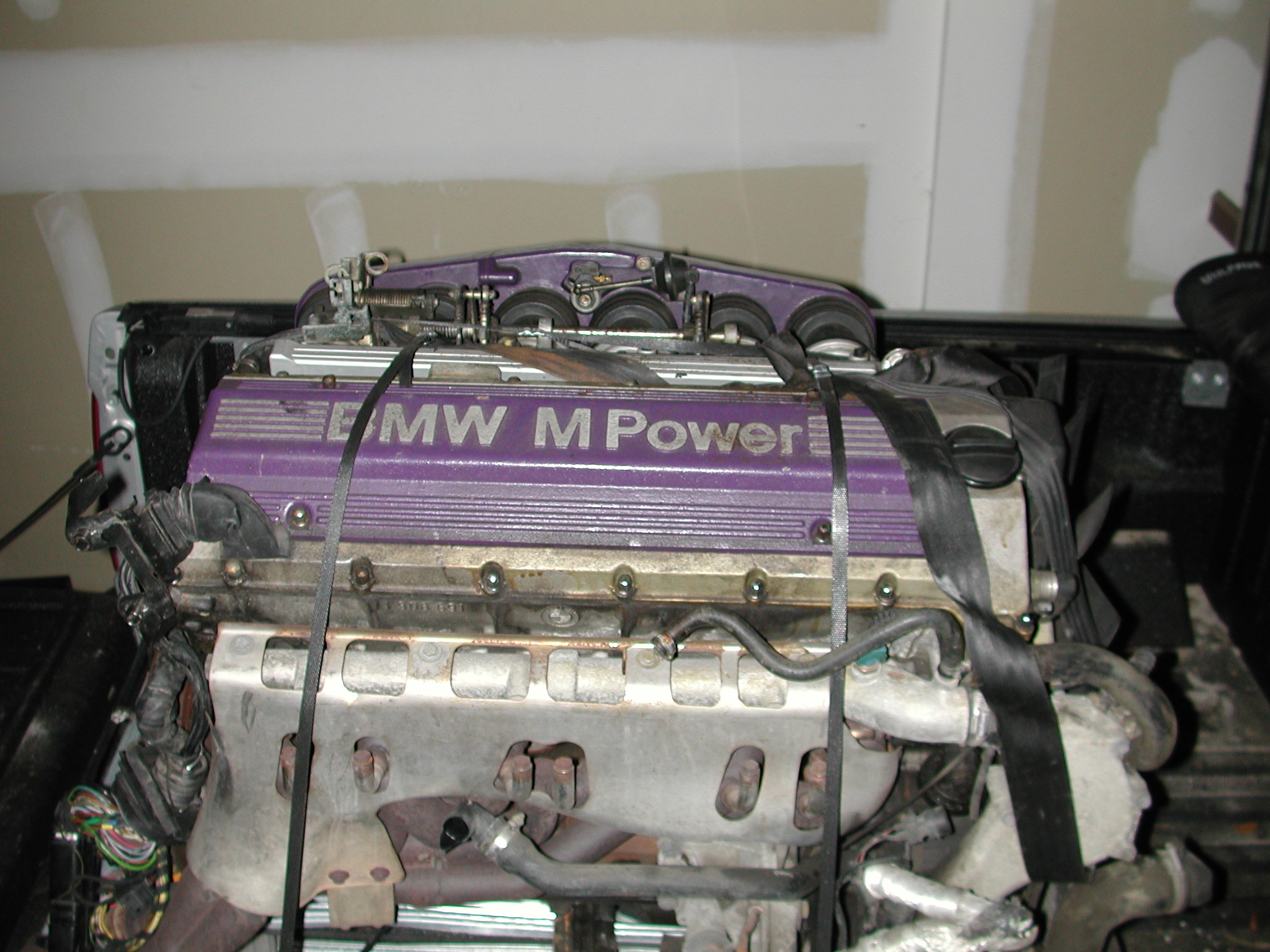
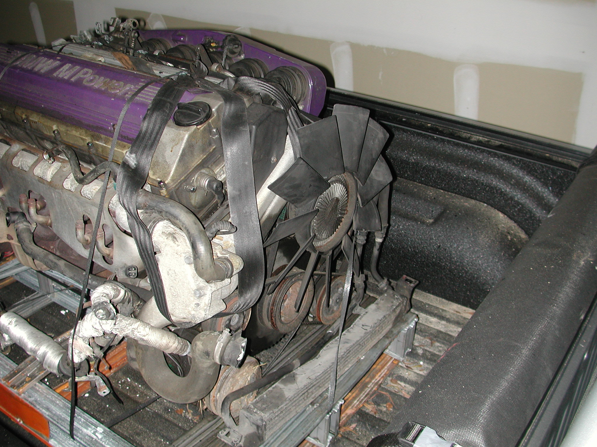
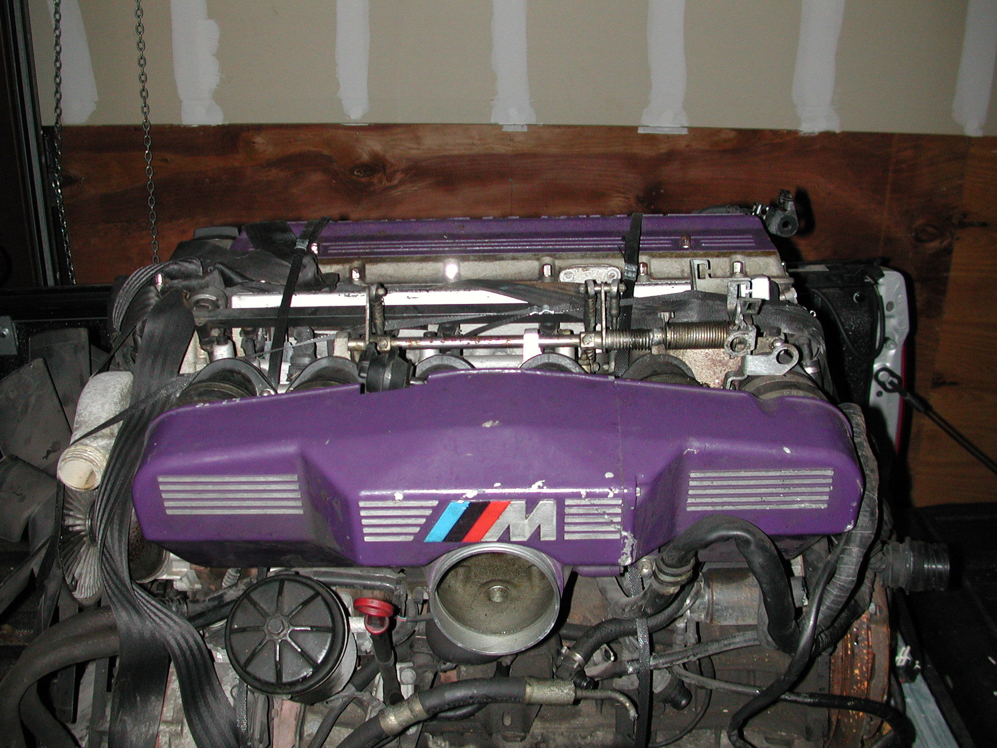
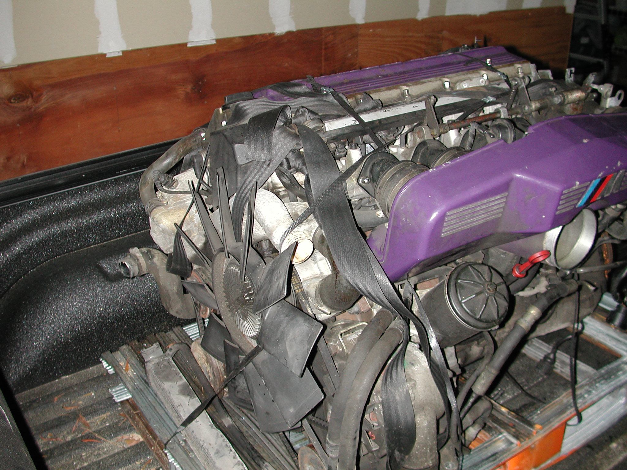
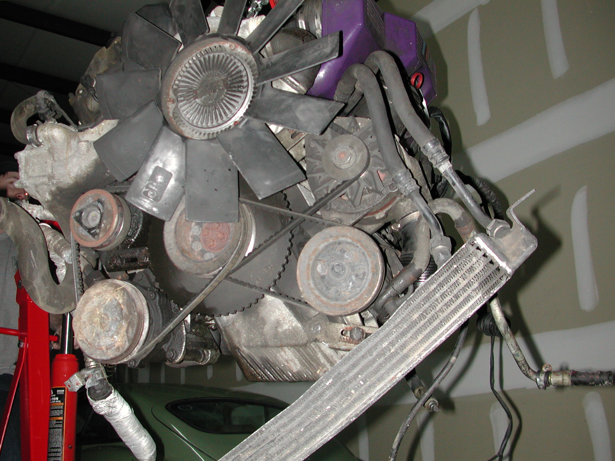
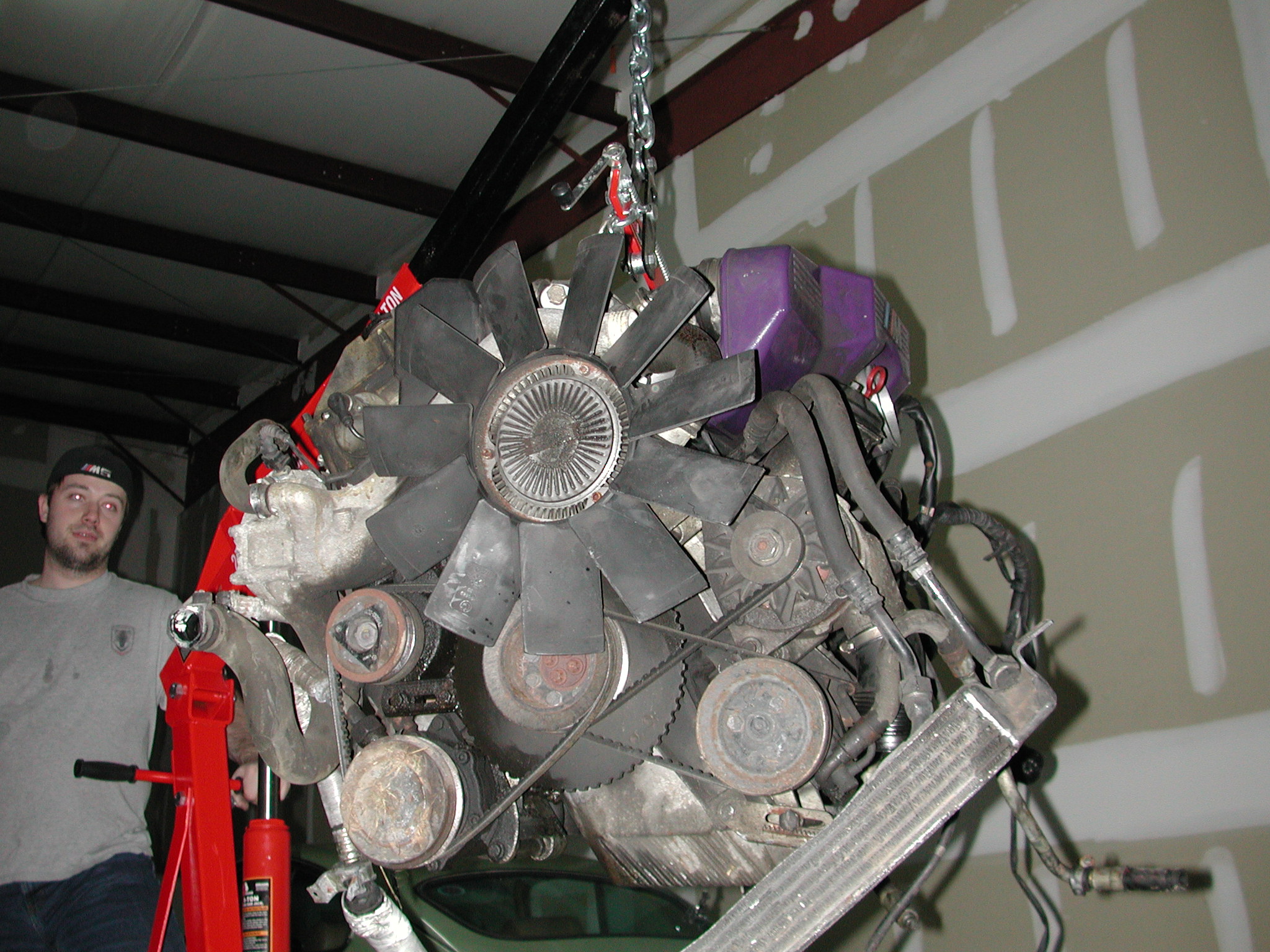
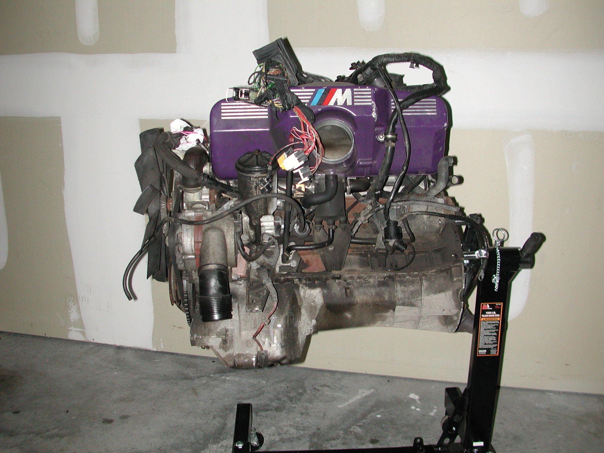
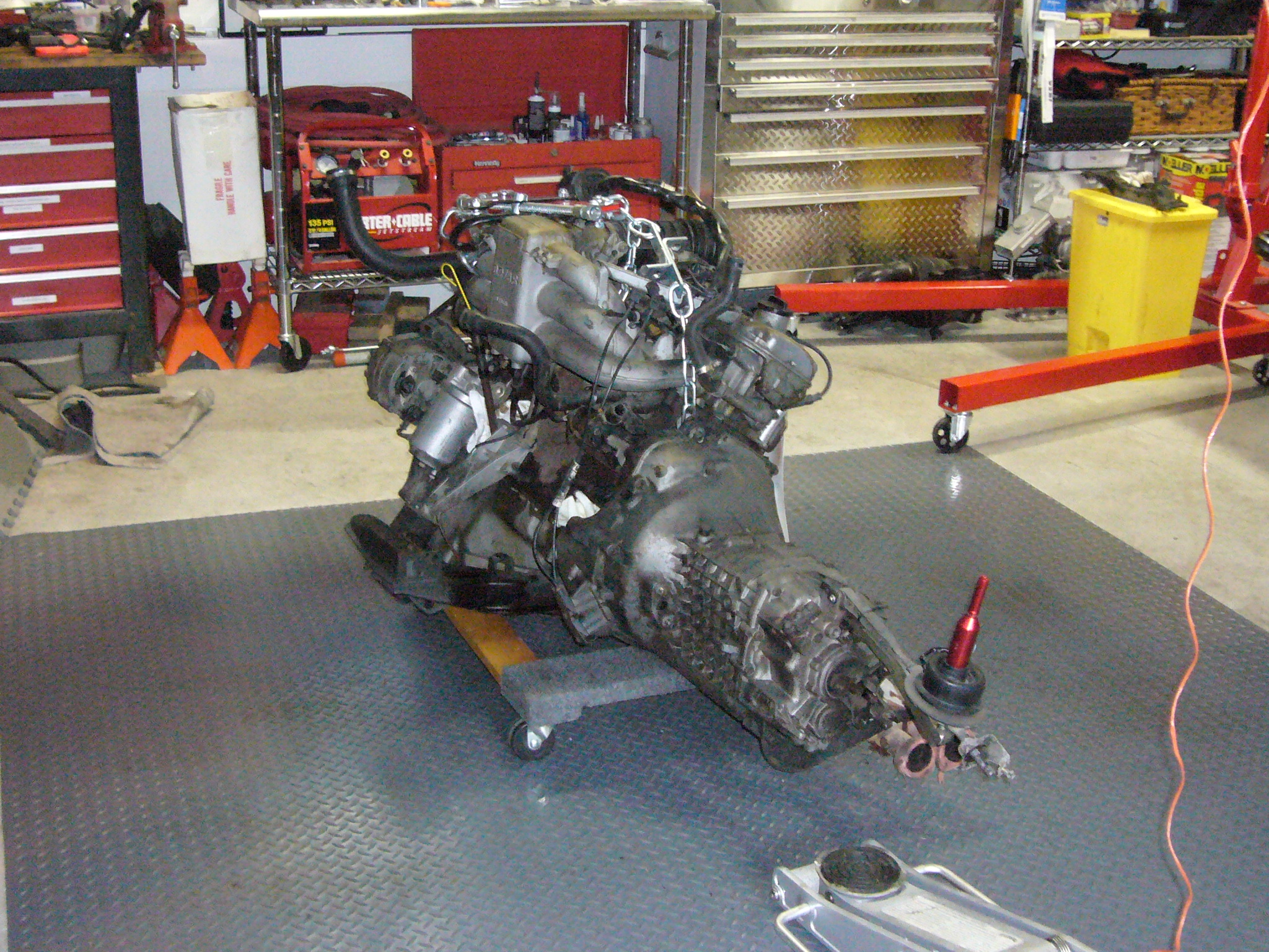
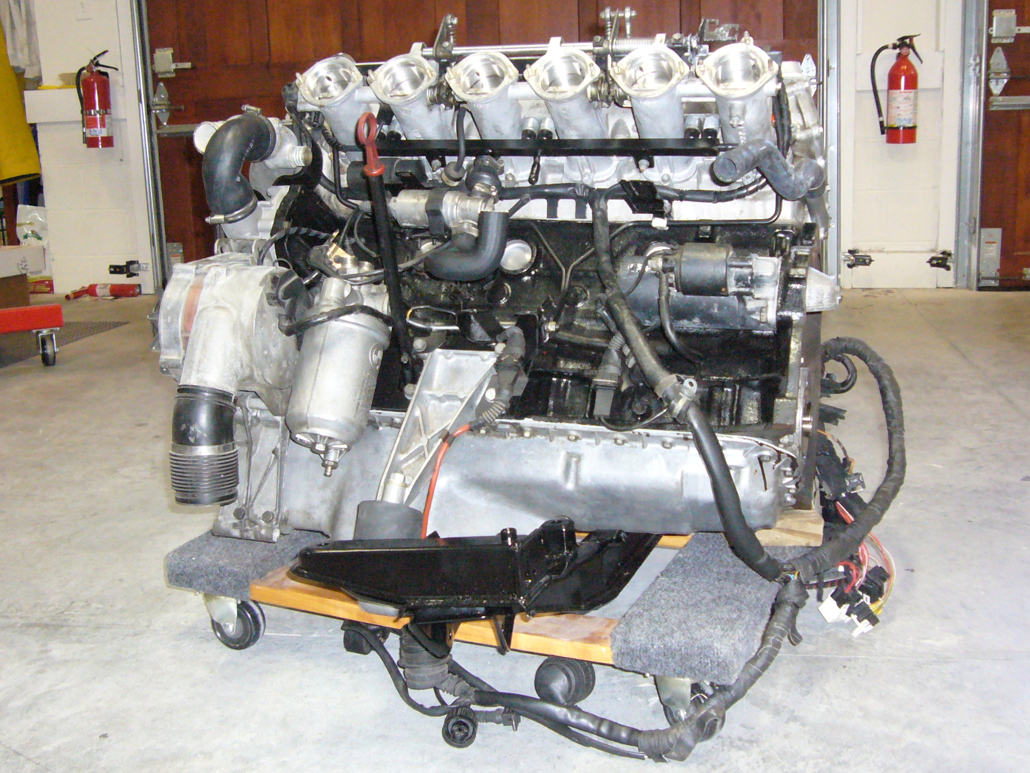
Here are some pictures of the motor when it was received. Needless to say I was not impressed with the packaging.
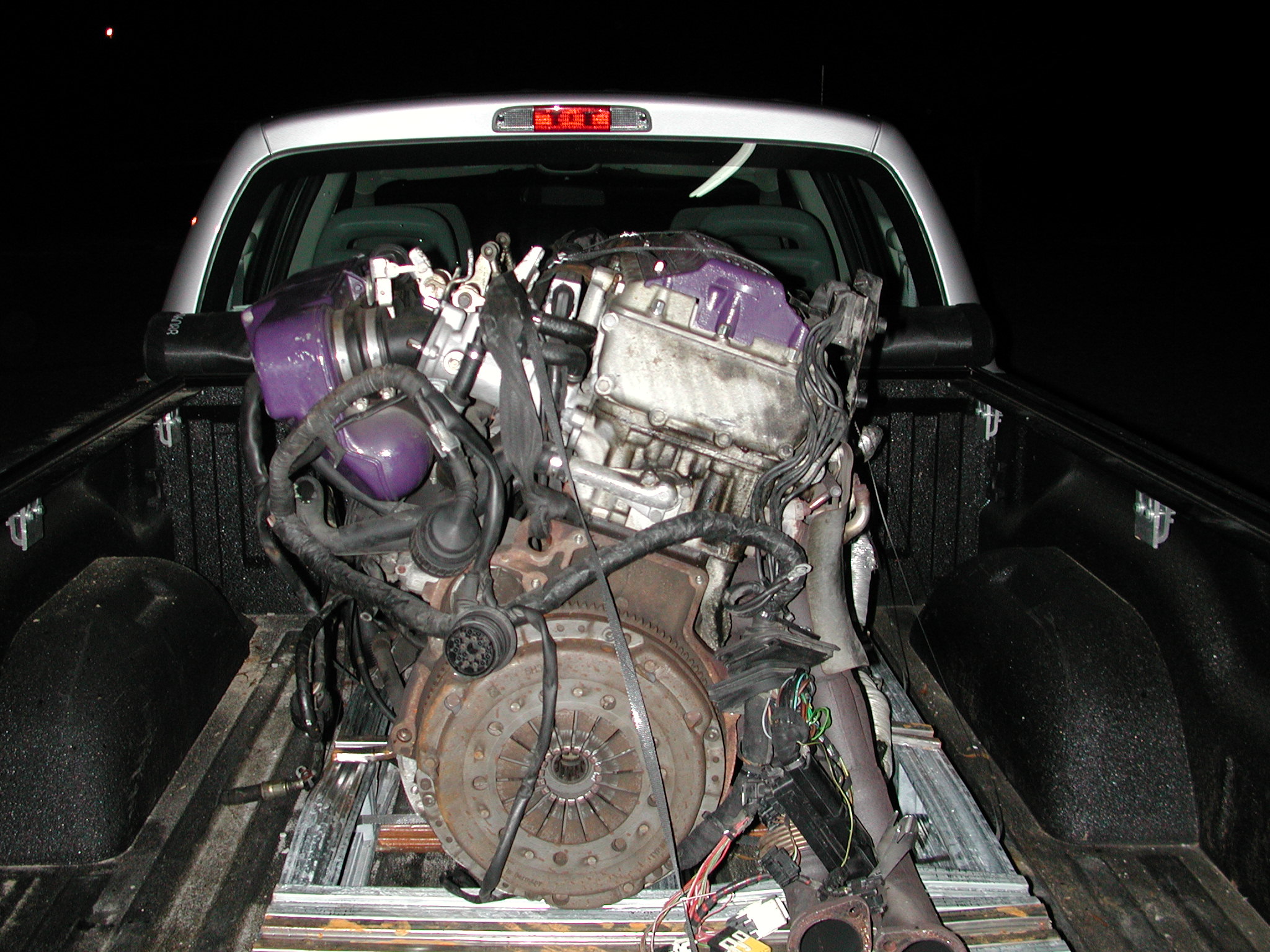
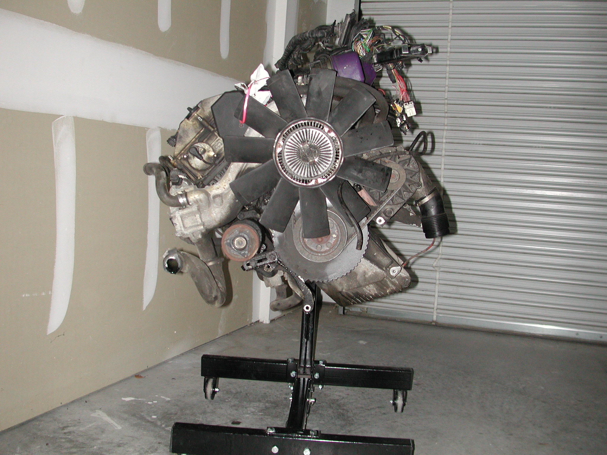
Now at this point I really want to make sure that safety comes first. The only way to do any work on the motor safely at this point is to put it on an engine stand.
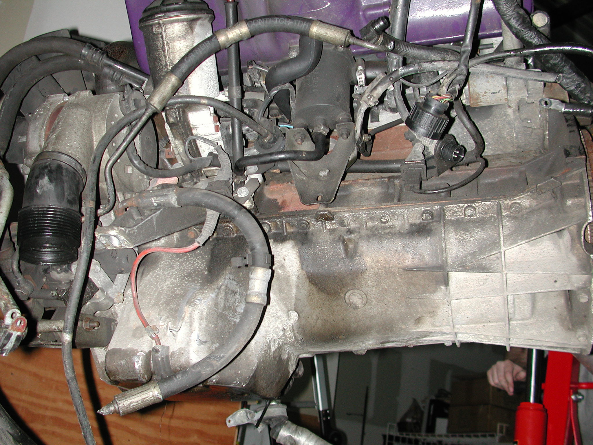
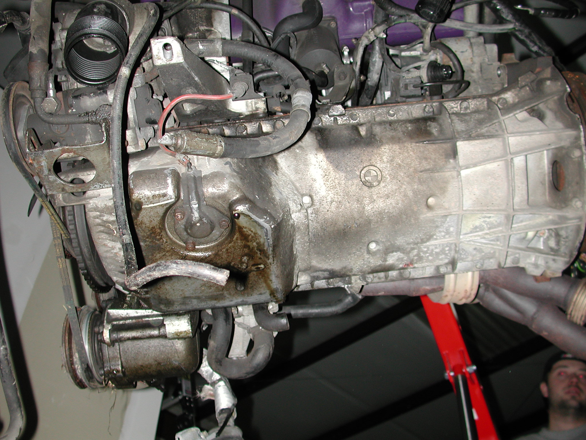
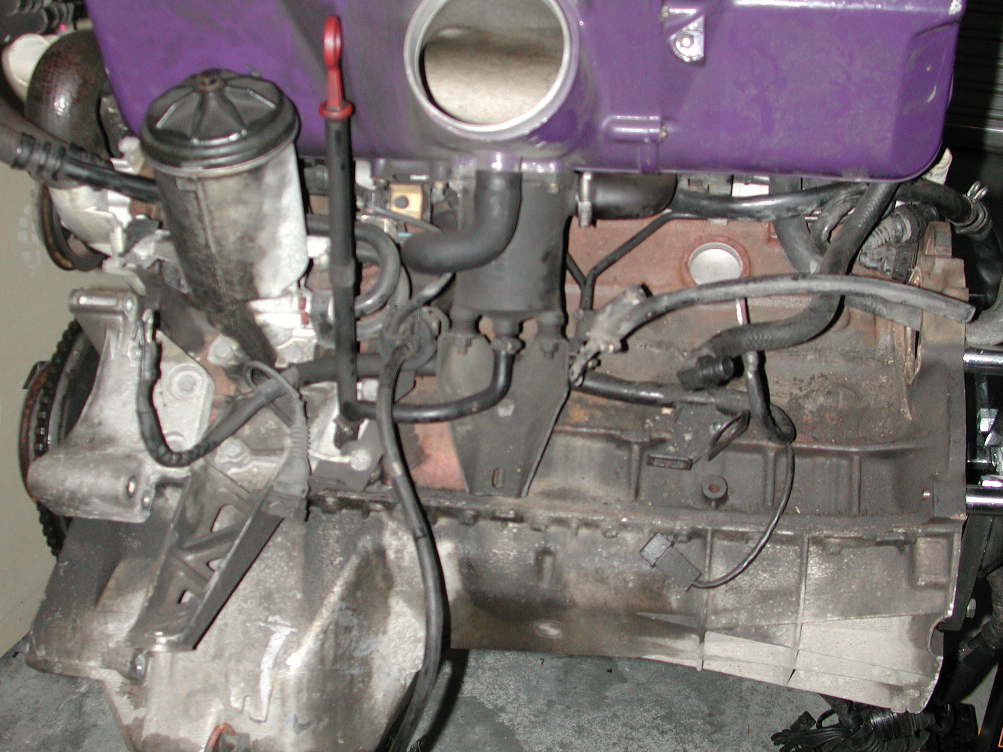
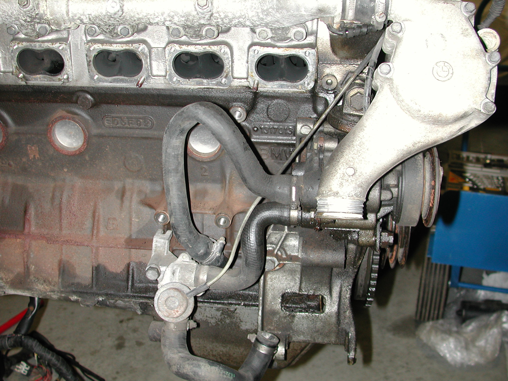
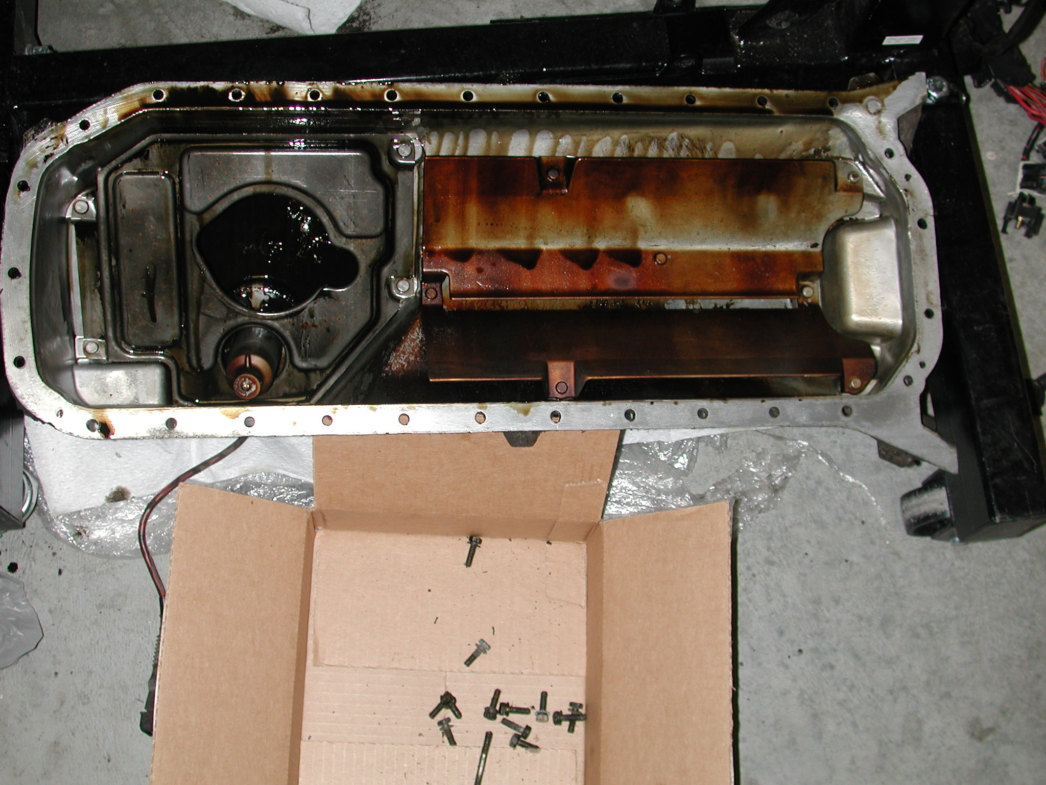
In these pictures I had taken the motor off of the pallet and was inspecting the underside, along with doing taking pictures of how things are assembled. I cannot stress enough how important it is to take these pictures. These will help you put the motor back together correctly considering the work you are about to undertake.
What cannot be easily seen is that the oil pan is cracked. I am not sure this came as a result of the shipping reopening a weld that was used to repair a crack before or if this was caused by the accident. The good news is that I never planned to use the oil pan so the damage would have no effect on the project.
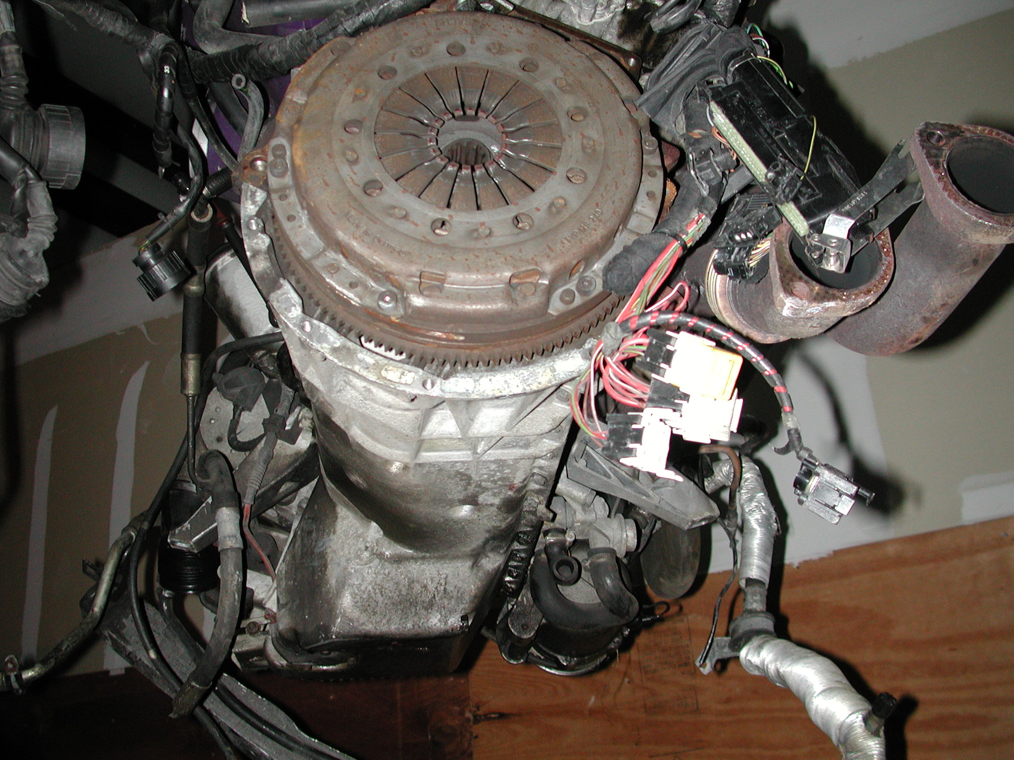
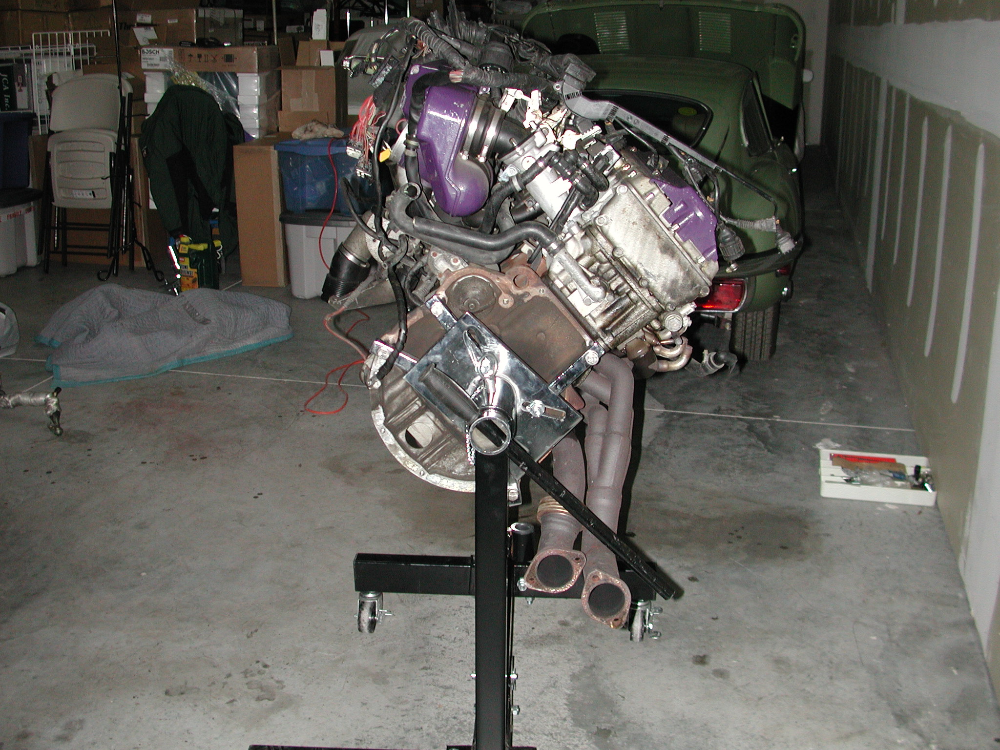
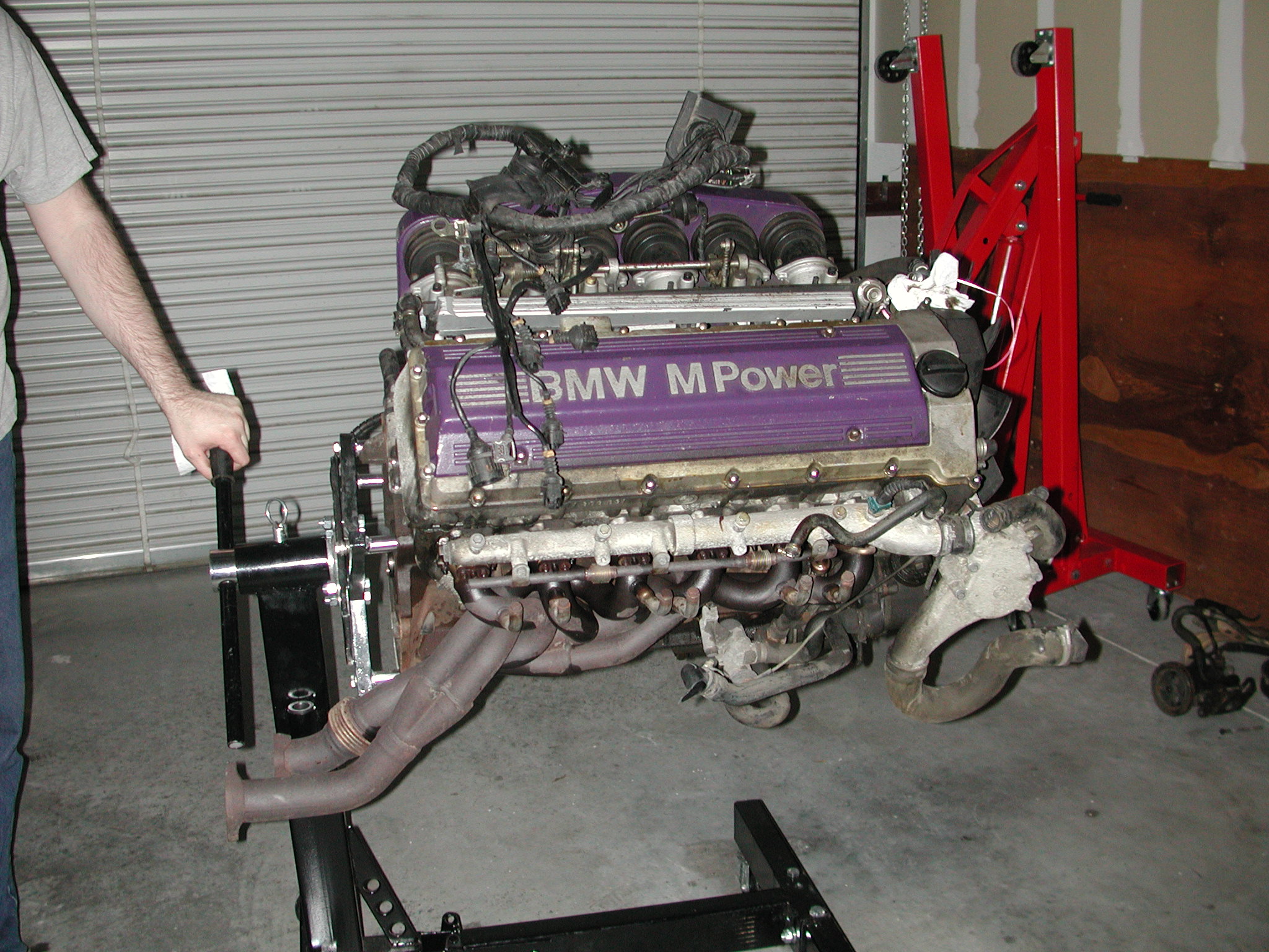
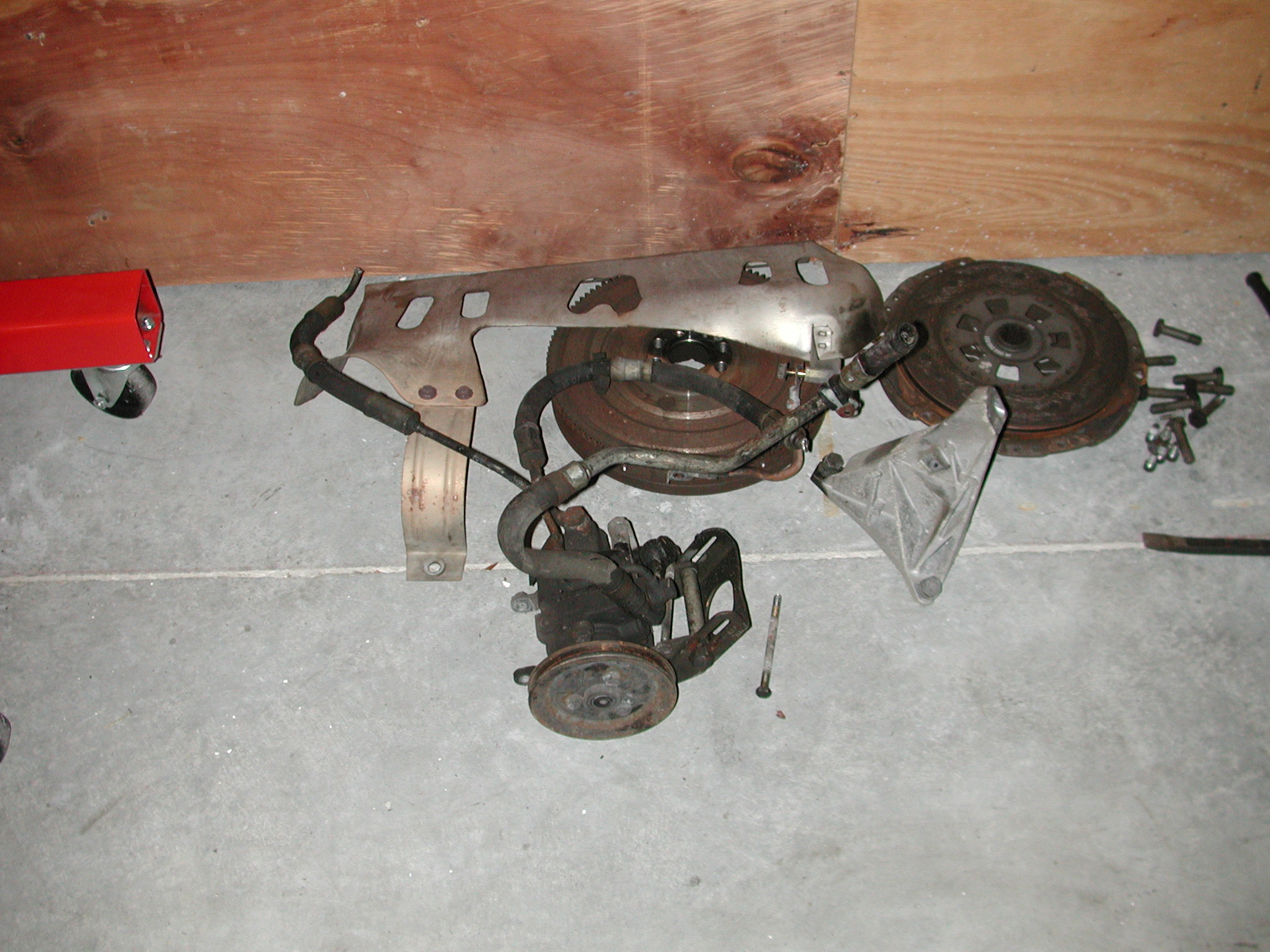
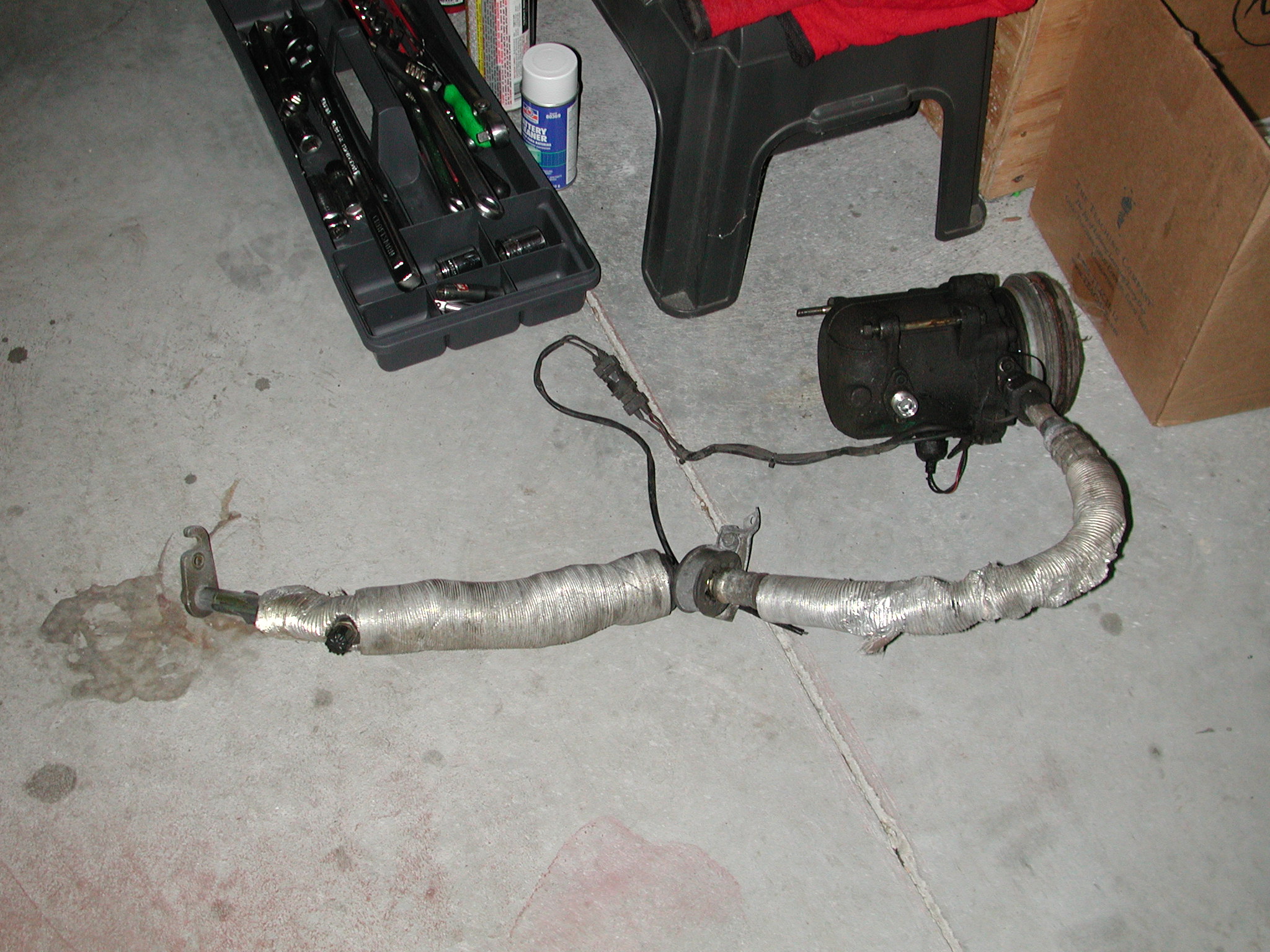
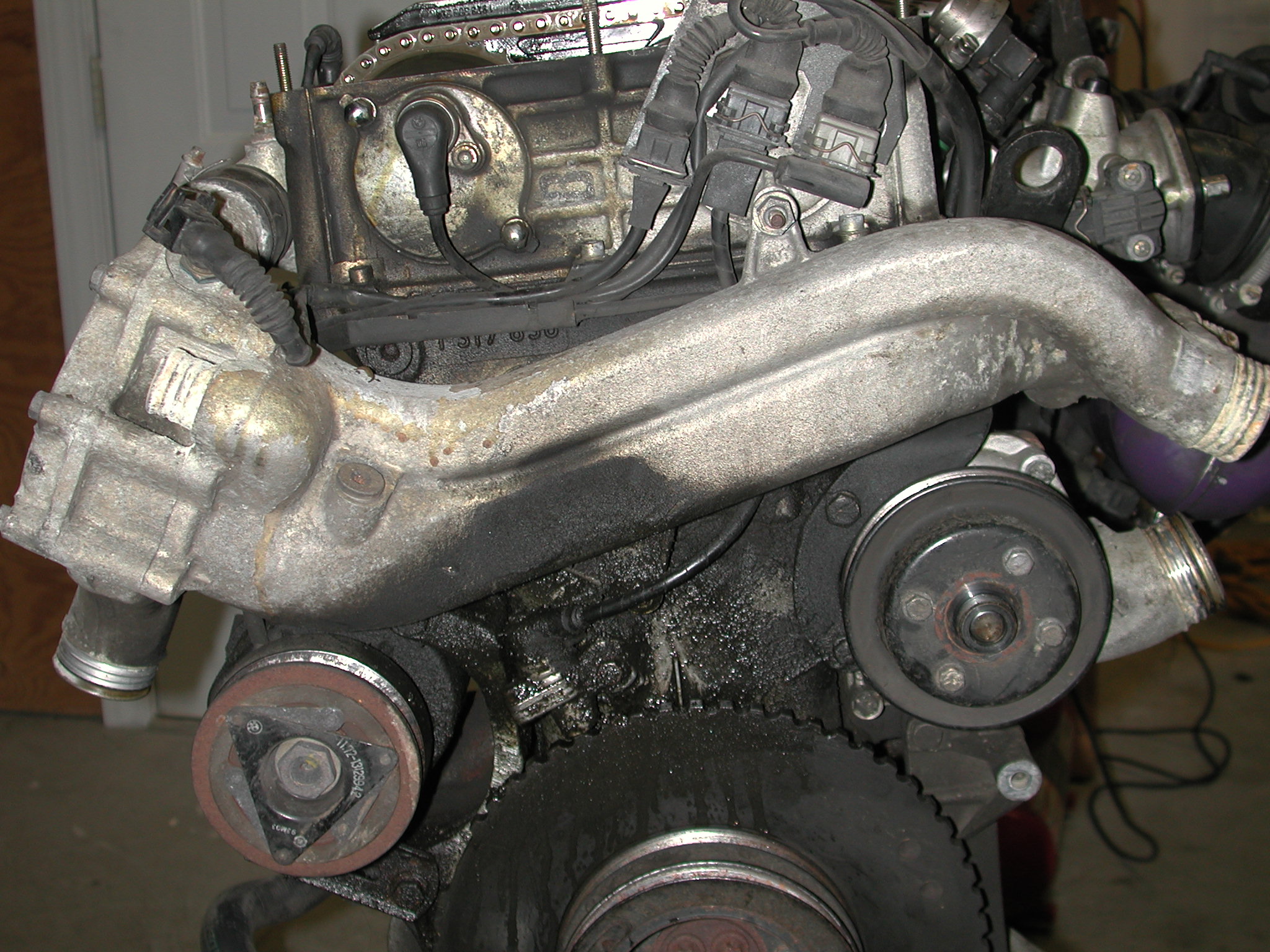
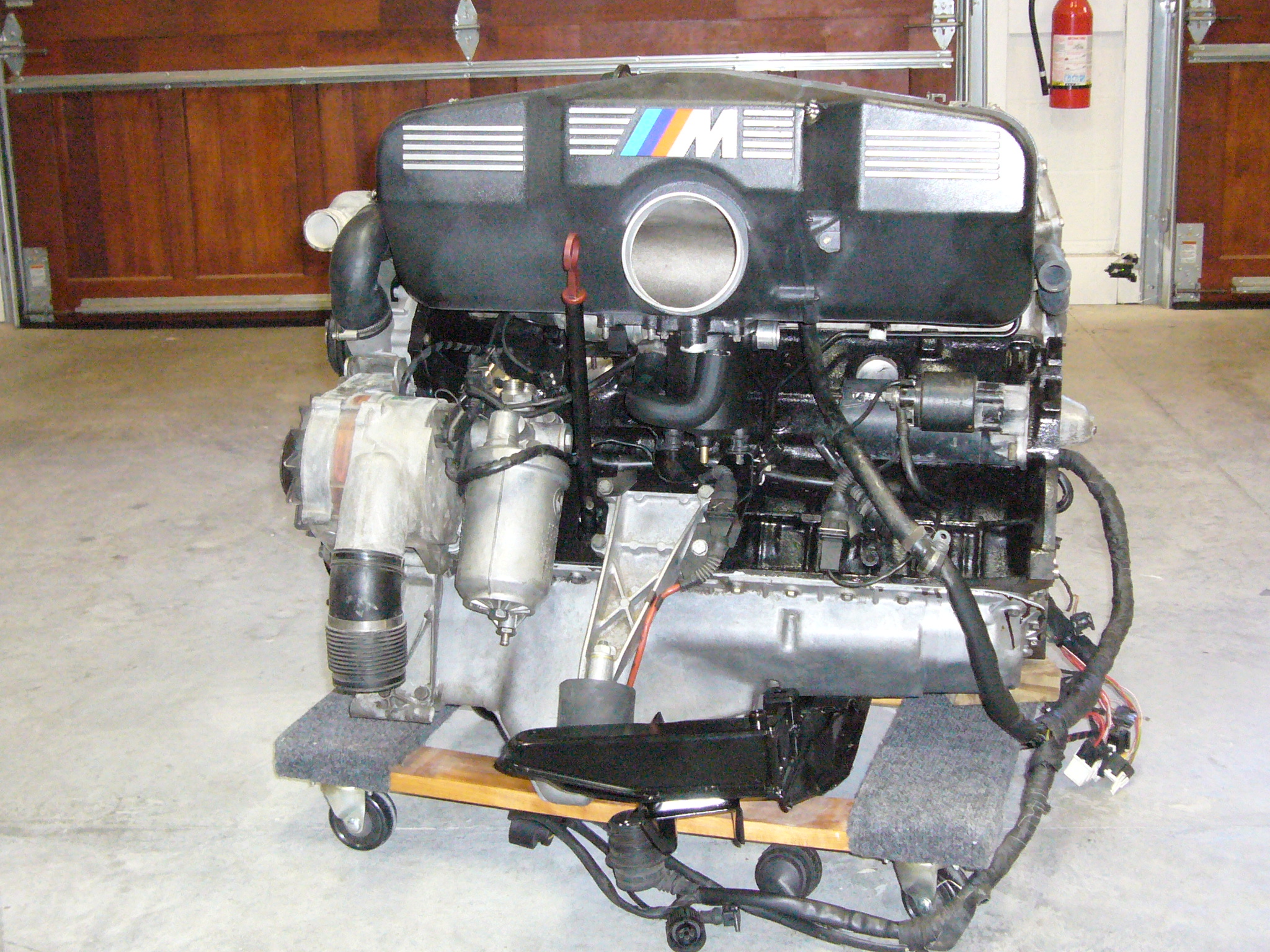
Now that the engine is on the stand. I took some more reference photos. As shown in the first round of pictures I have already removed the power steering pump, AC compressor, passenger side engine mount, header heat sheild and flywheel and clutch assembly.
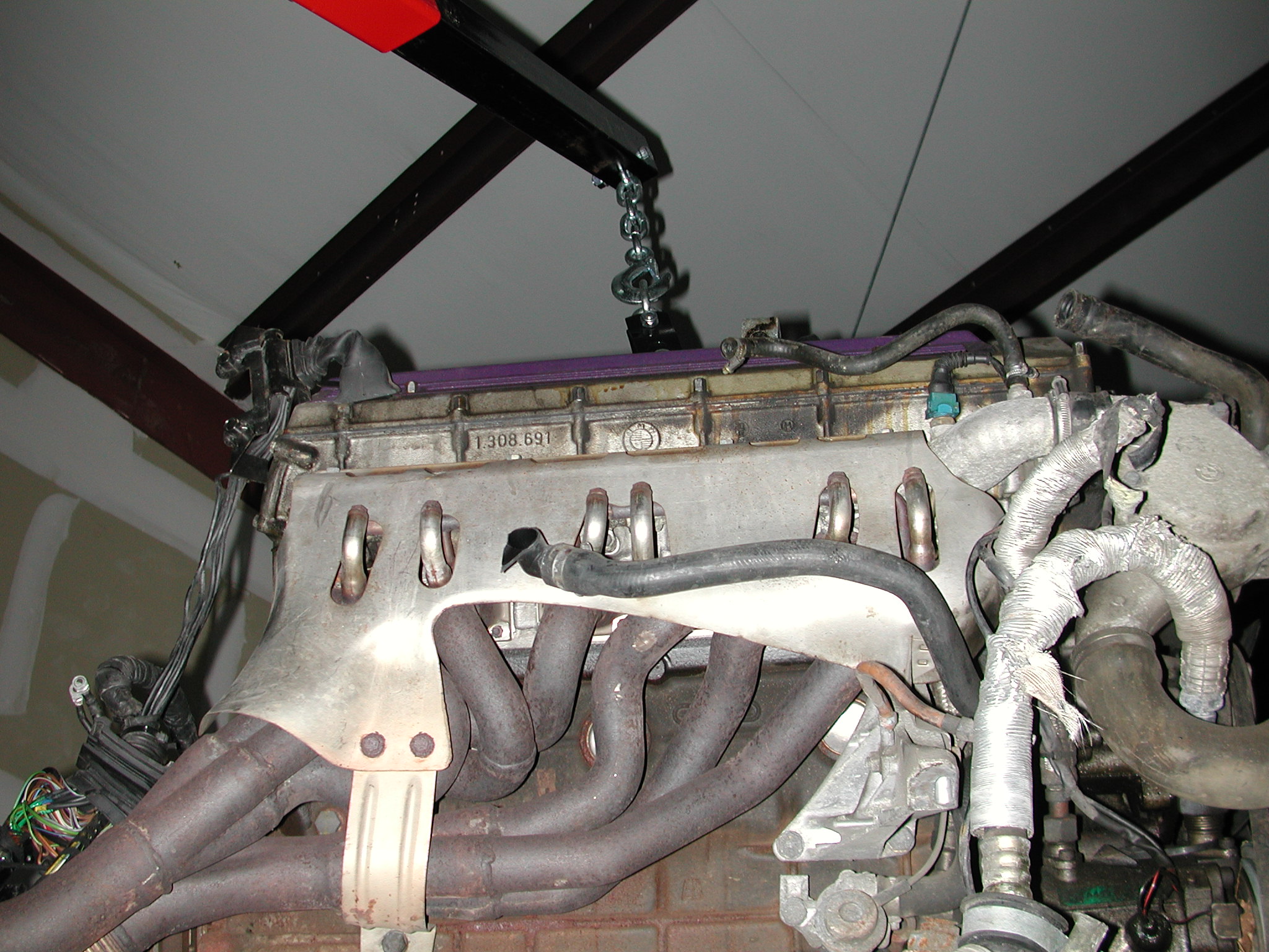
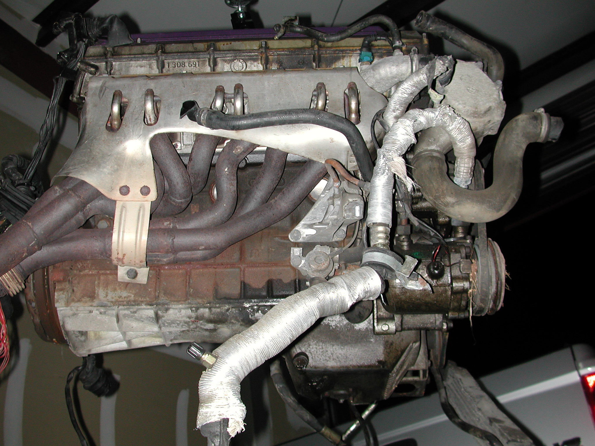
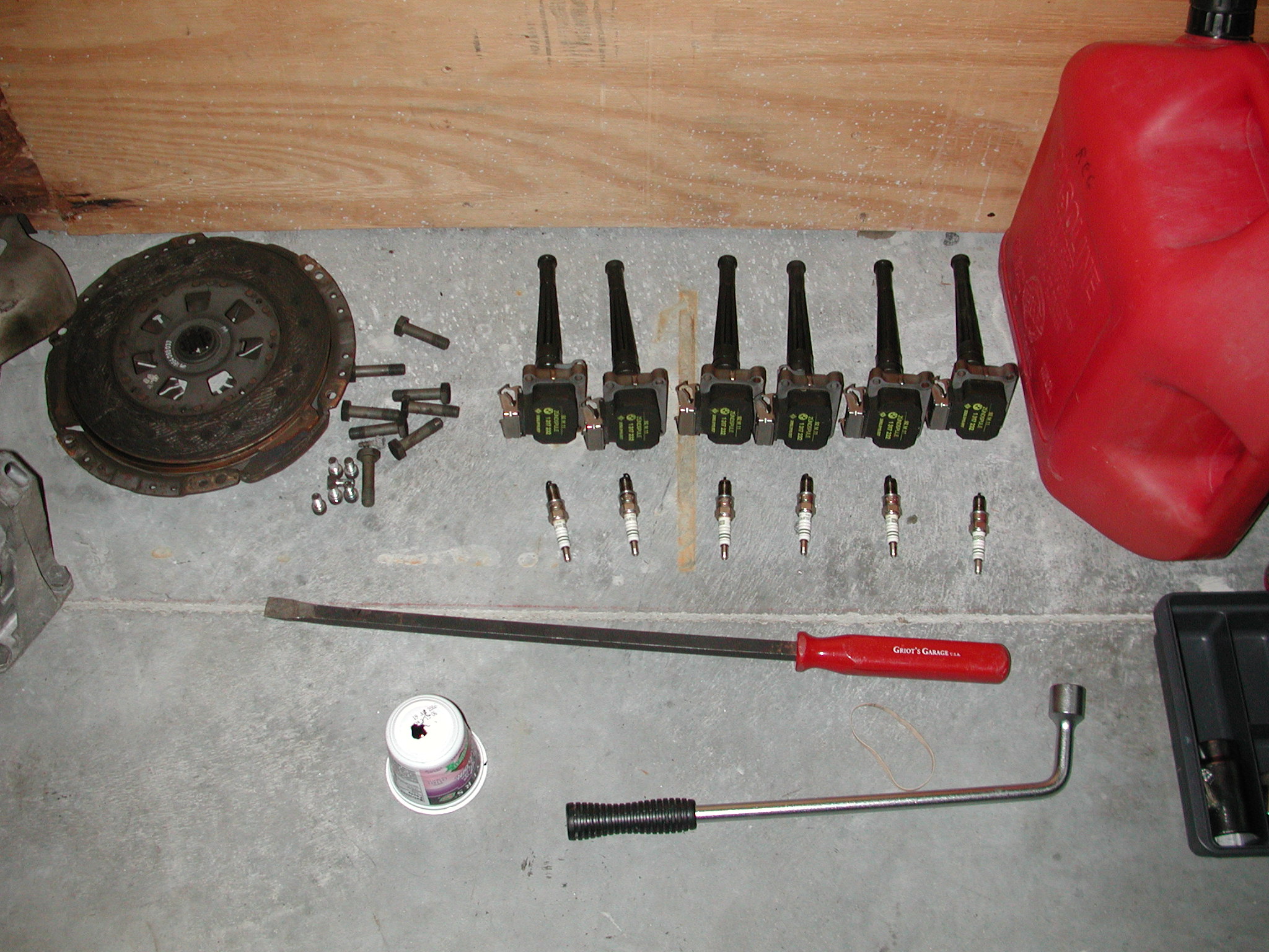
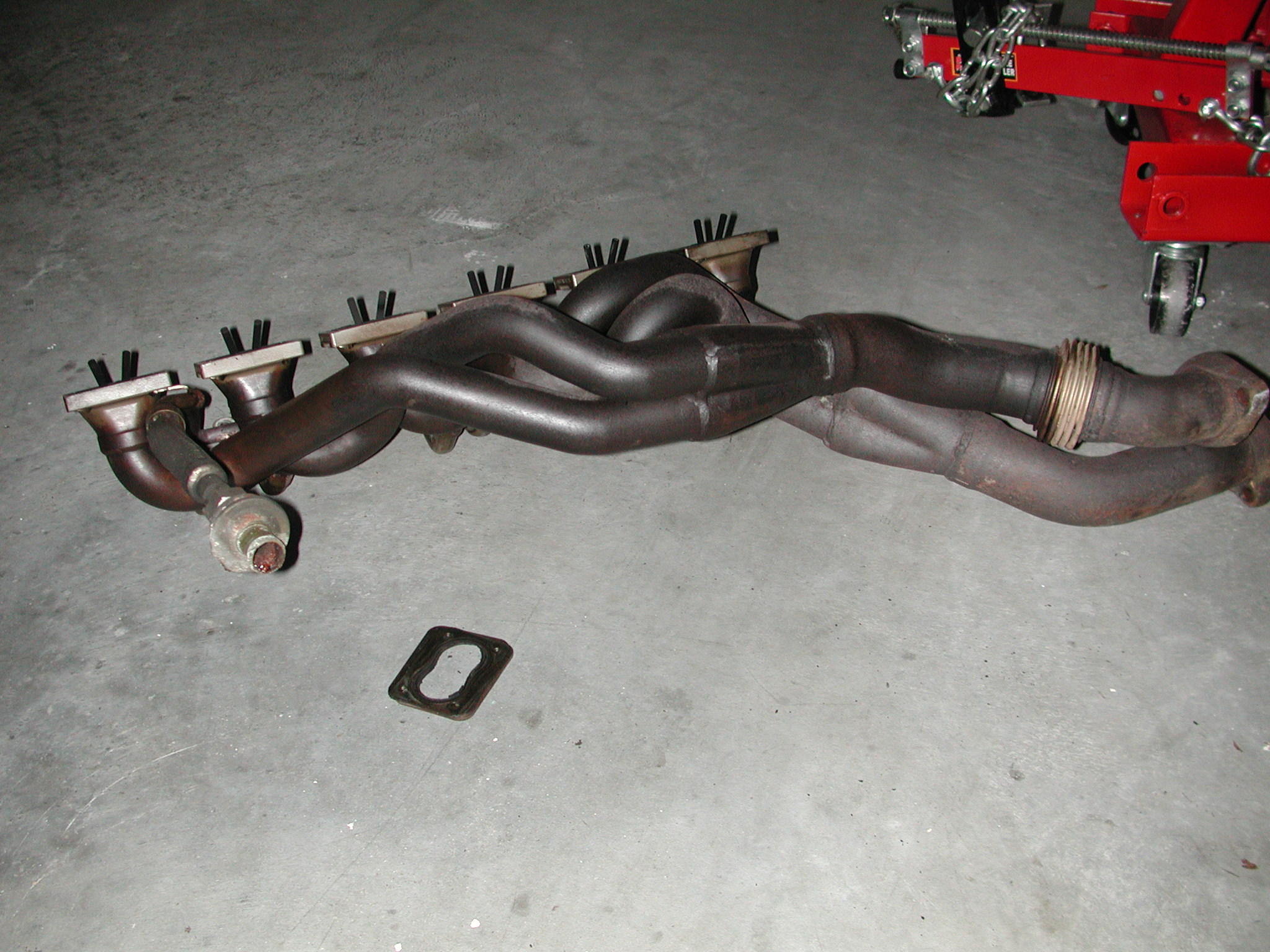
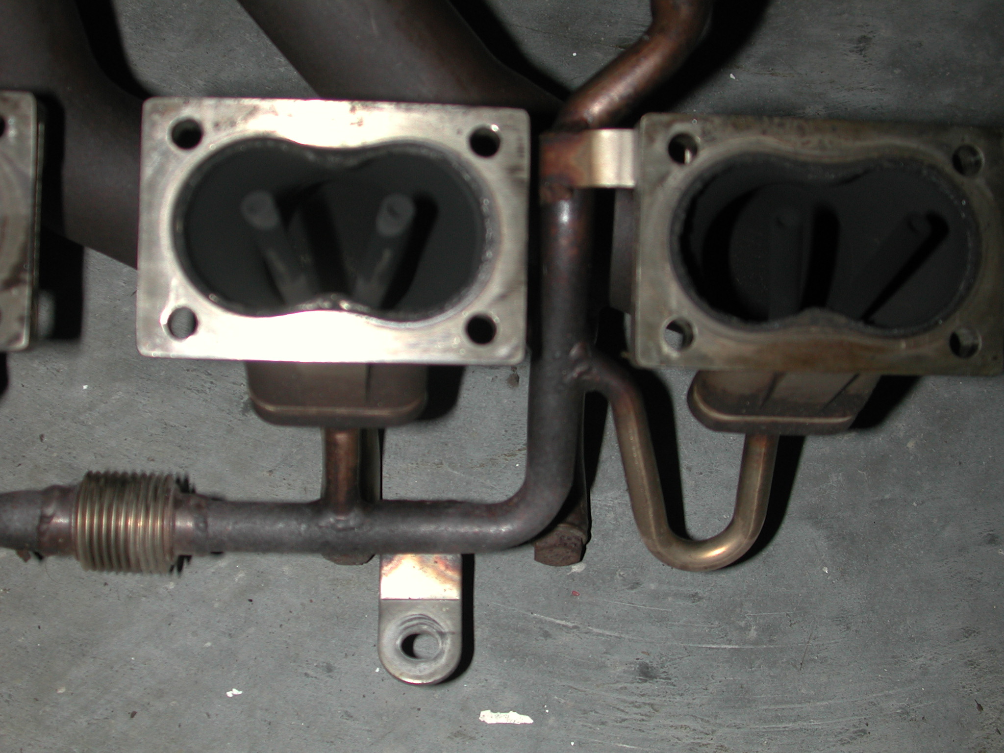
After this I decided to remove the coils and the spark plugs. This allowed me to do the leak down test on the motor. I also removed the headers which I took some pictures of. I knew I was not going to be reusing these because of the fact they must be modified to fit in the car, M88/3 headers bolt on, and I am not using the air pump system. Lastly I decided to remove the starter and alternator.
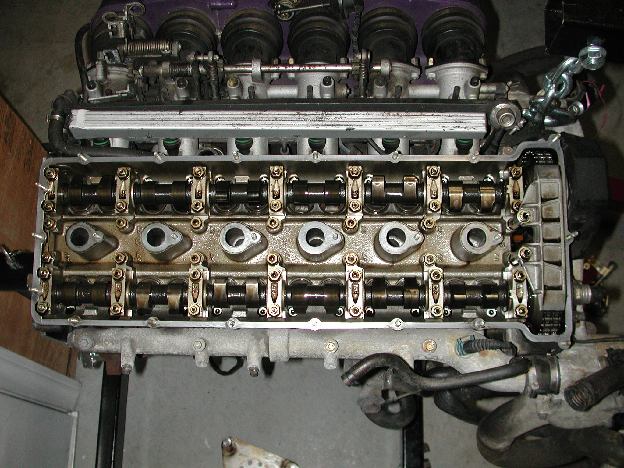
The next step was to see inside the beast. I really wanted to get a sense of what the internals looked like, so I pulled the valve cover to expose the cams. I was plesantly surprised with what I found. The cams looked great and everything looked really clean.
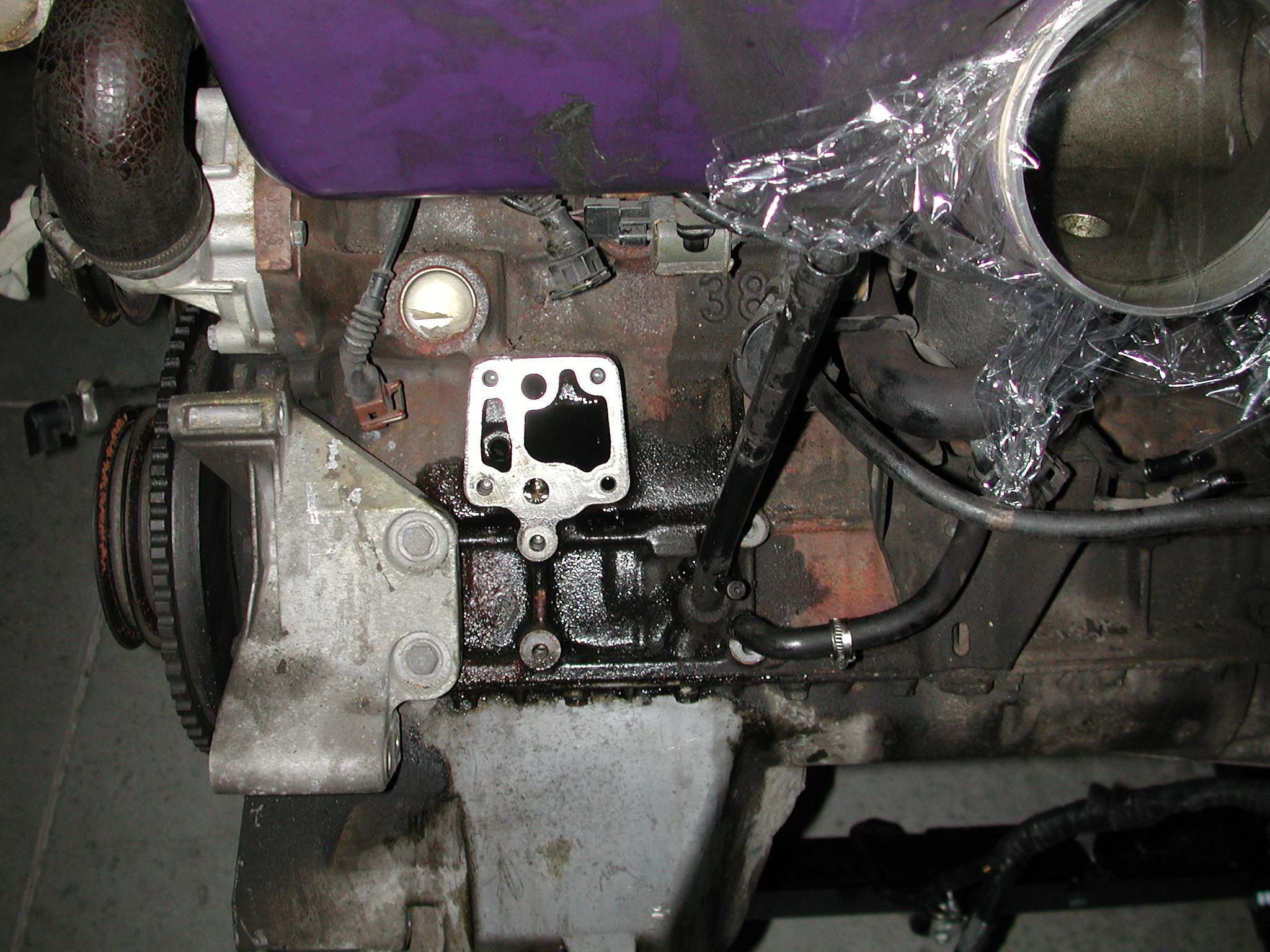
I then pulled the oil filter housing off. I knew that I wanted to use the M88/3 or S38 B35 oil filter housing so the E28 US M5 oil cooler that I had in my car would bolt up. I also knew that the driver's side engine mount would need to change so that was removed.
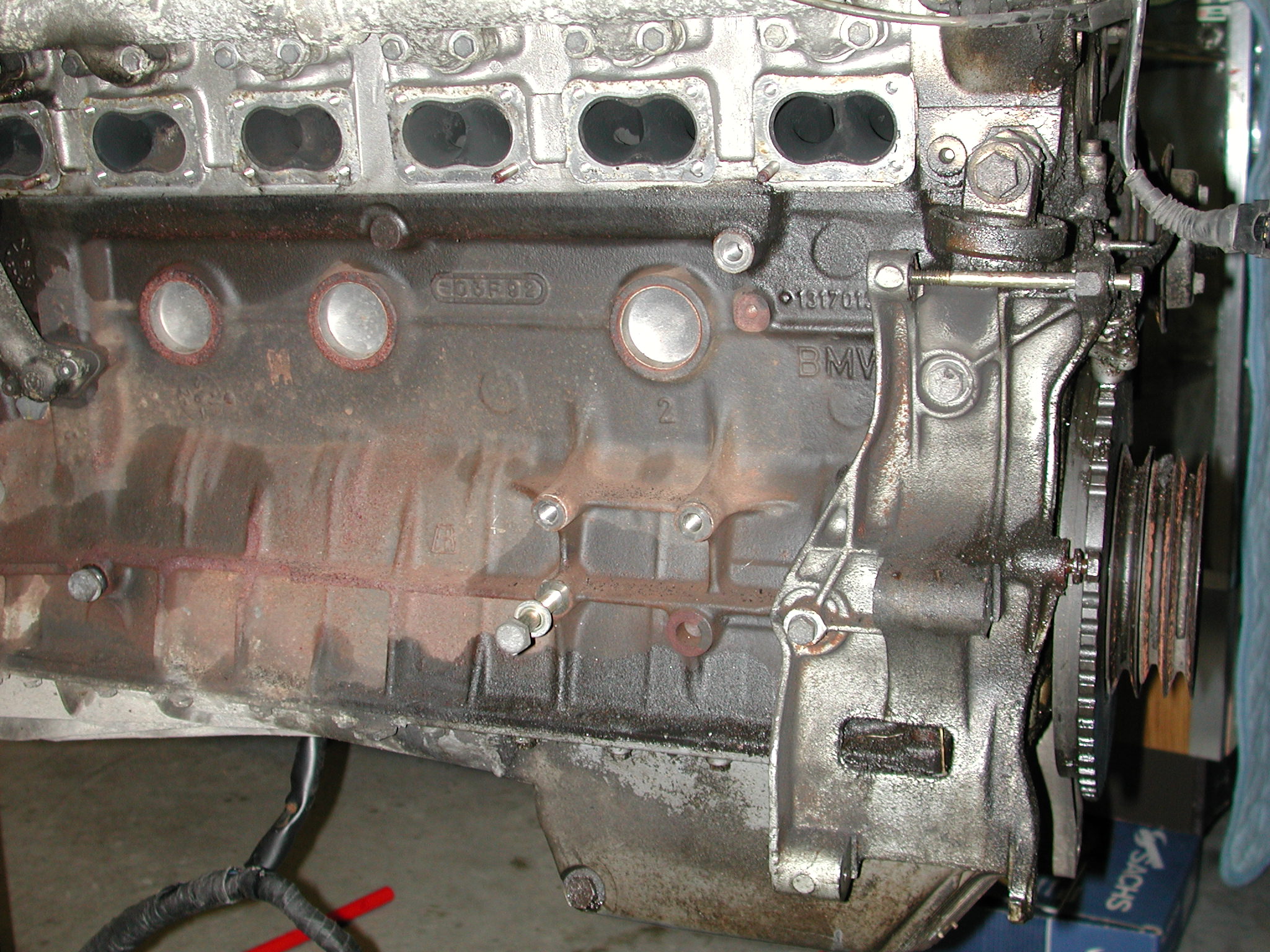
I followed this up with some reference photos before further disassembly.
I then proceeded to remove the thermostat housing and coolant cross tube. What I then noticed was that it seems the timing chain tensioner was leaking and causing the front of the motor to get covered in oil.
I decided that the next thing to do was to remove the air pump equipment. I was dead set on not wanting to use this when I put the motor in the car, but I decided I needed to remove it carefully just in case.
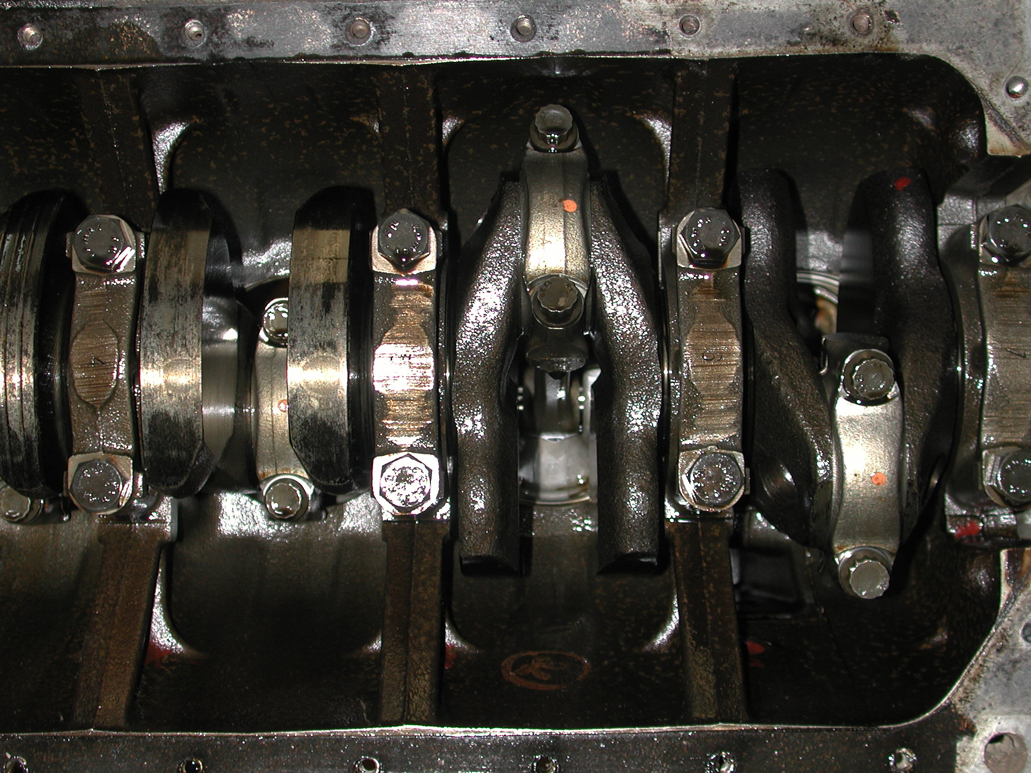
Because of the leaking tensioner I decided it would be good to pull the oil pan. What I found was again very pleasing. The bottom of the pan looked clean. The inside of the bottom end also looked great.
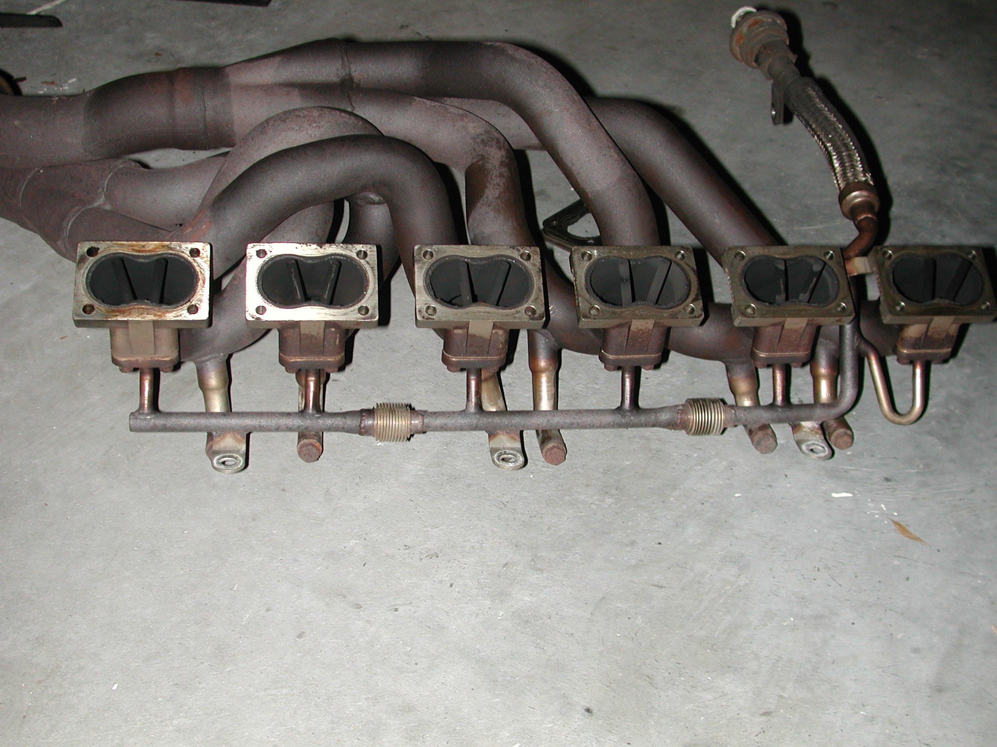
I took some reference pictures of the underside of the intake as there is a lot of plumbing under there. I also took some more bottom end photos.
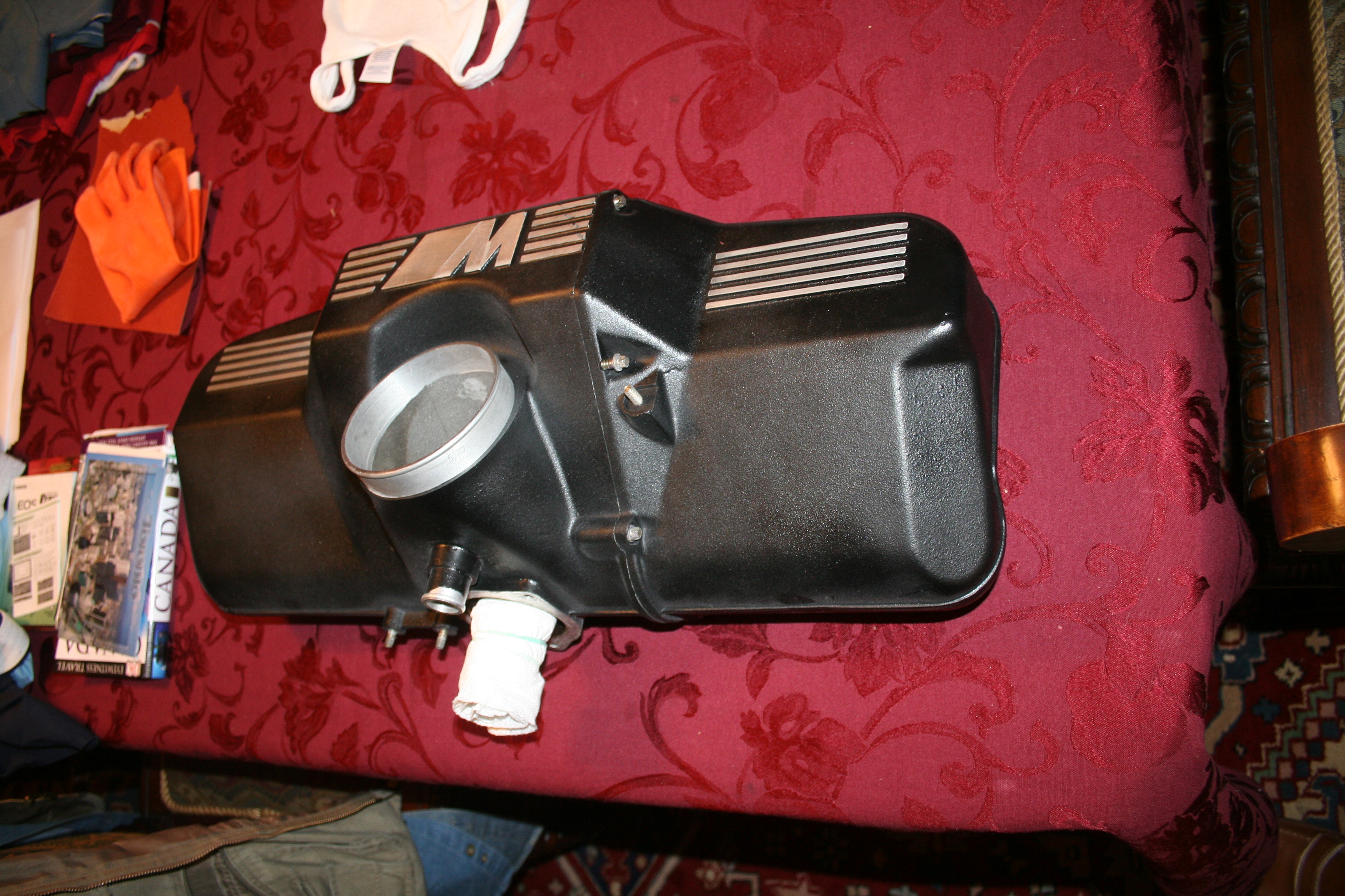
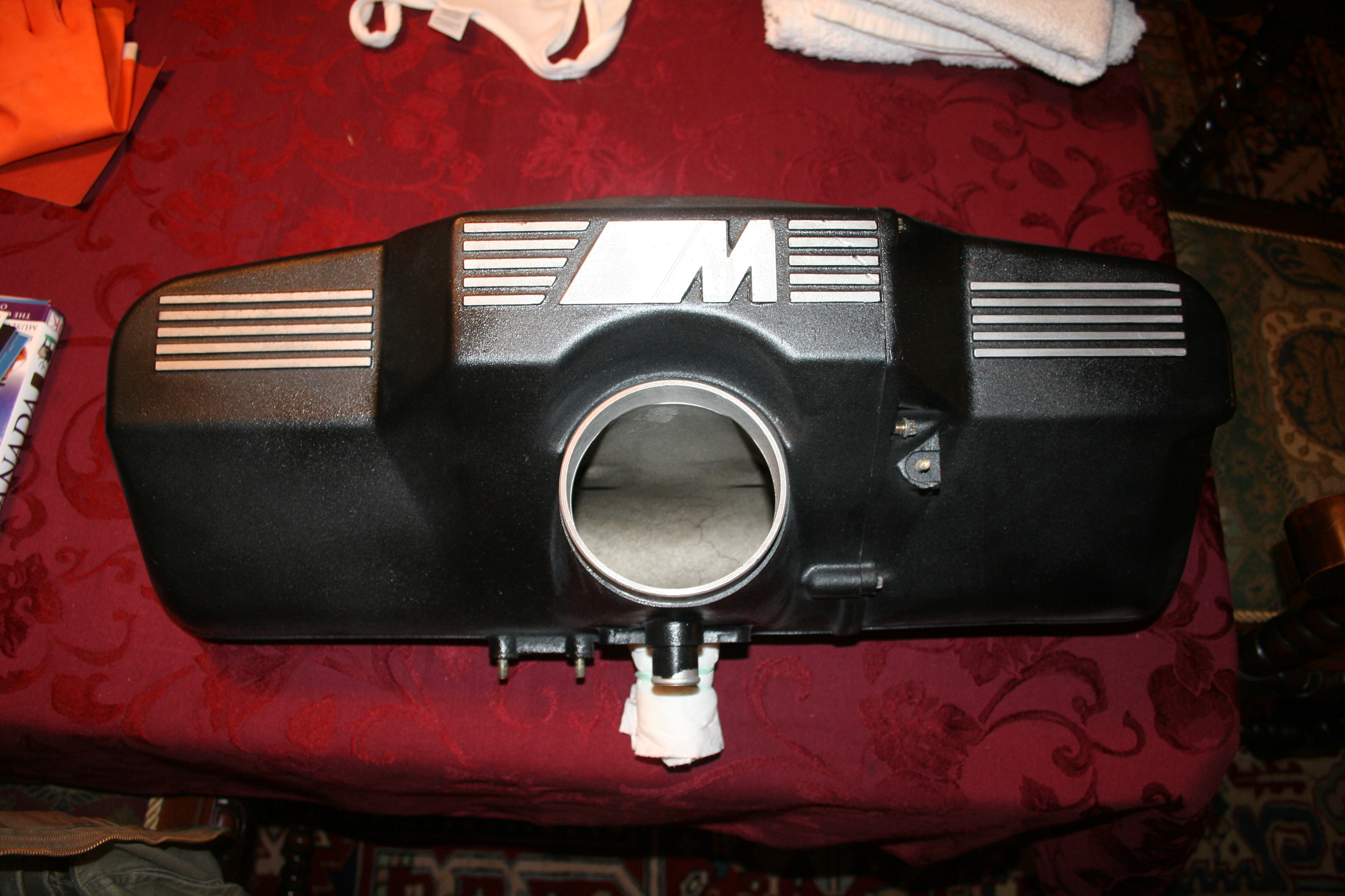
At this point I decided that it was important for me to remove the intake plenum. This would get a very large item out of the way and the work on refurbishing it along with the valve and coil covers could start.
When removing the plenum I also removed the oil separator valve and support bracket. I removed the oil separator valve from the plenum and found the inside to be quite dirty and also wanted to replace the rubber mounts at the bottom. Replacing the rubber mounts proved to be the wrong decision. The rubber mounts we stuck in the bottom of the separator. I tried in vain to remove them, but ended up causing so much damage to the separator I had to replace it.
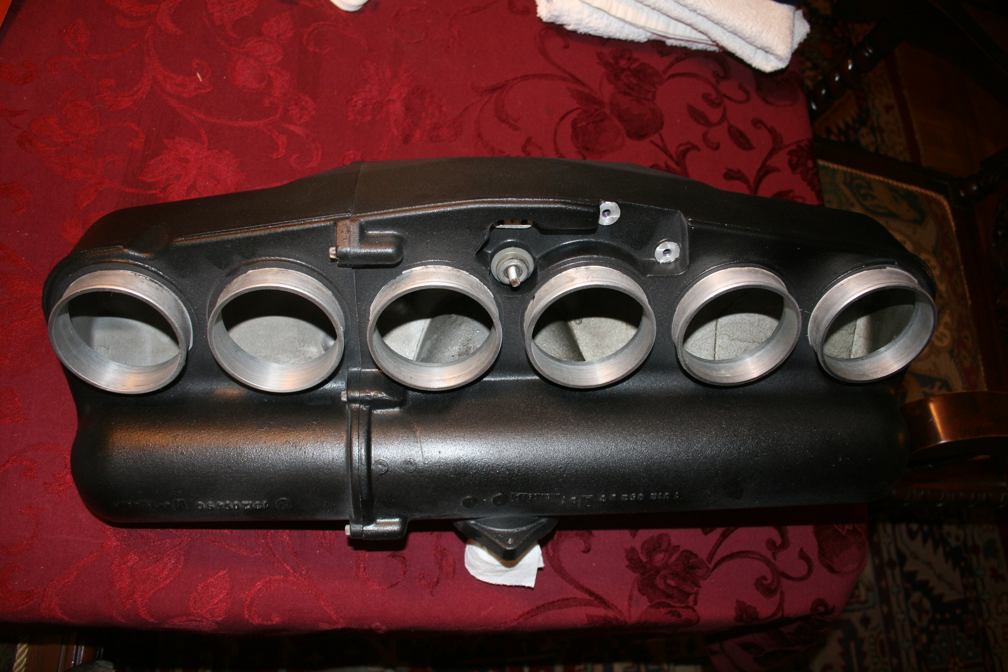
Now I also split the plenum to make sure that the vacuum acutated flap that is in the center of the plenum was working smoothly. This also allows easier access to refurbishing the plenum.
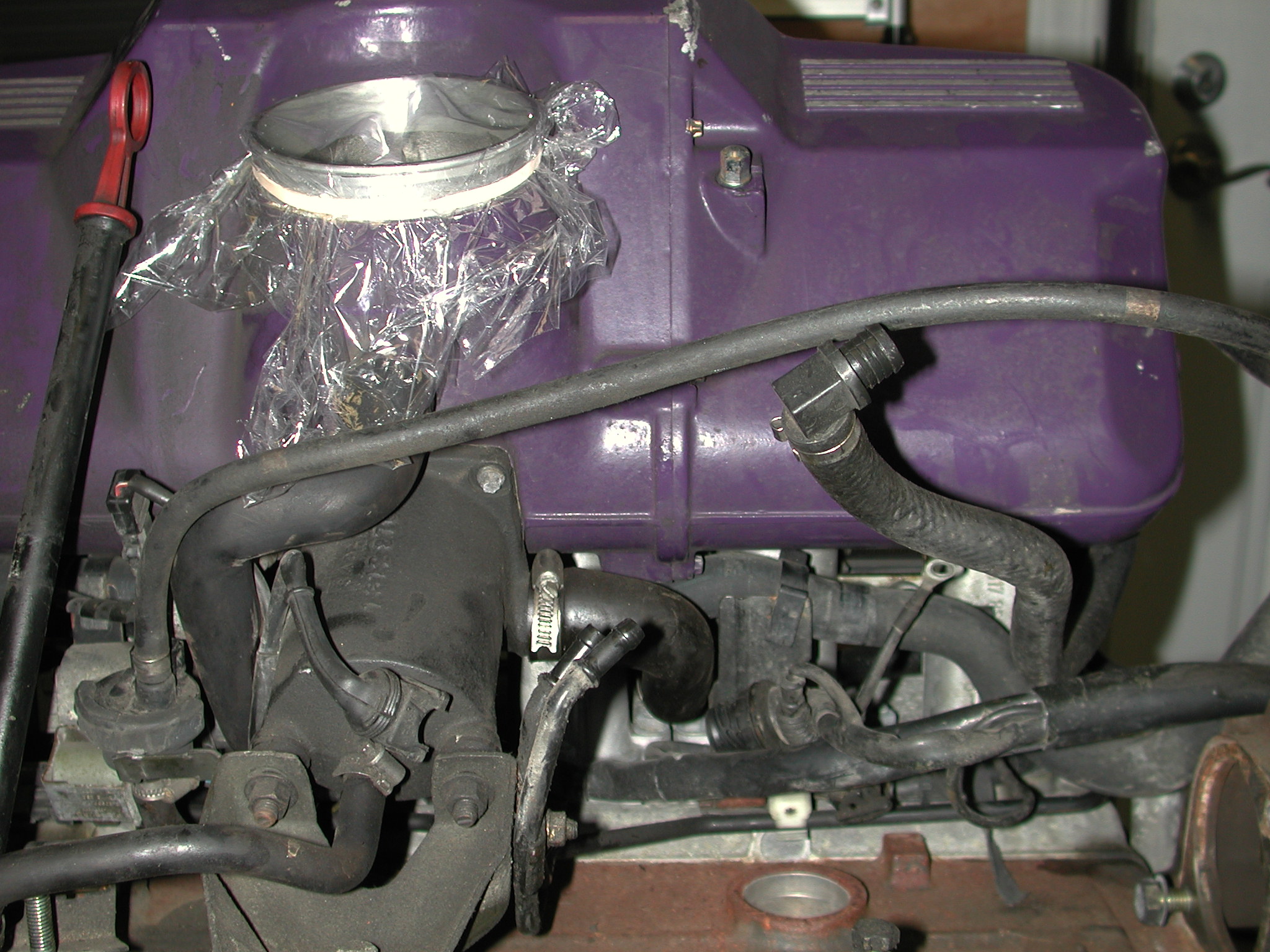
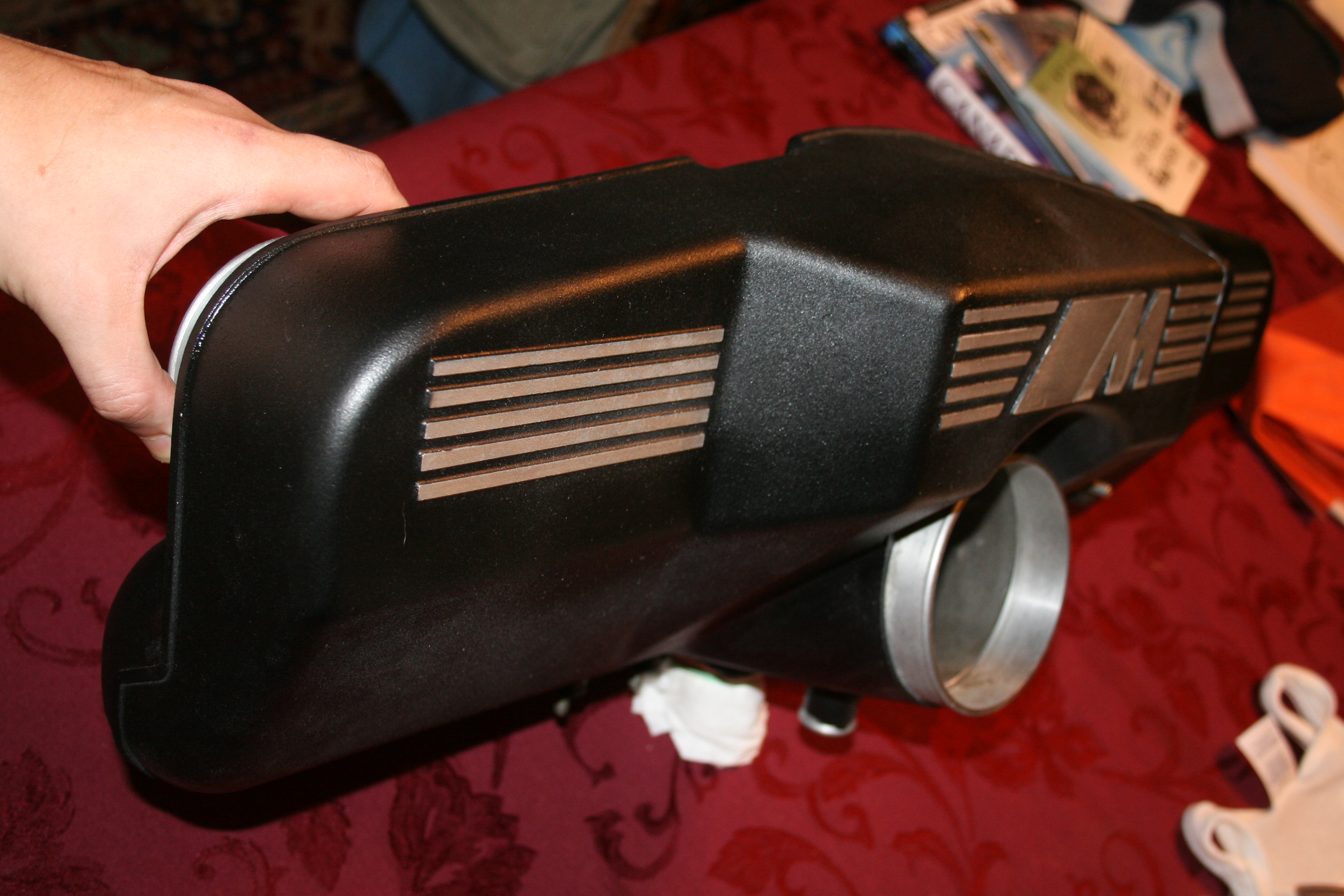
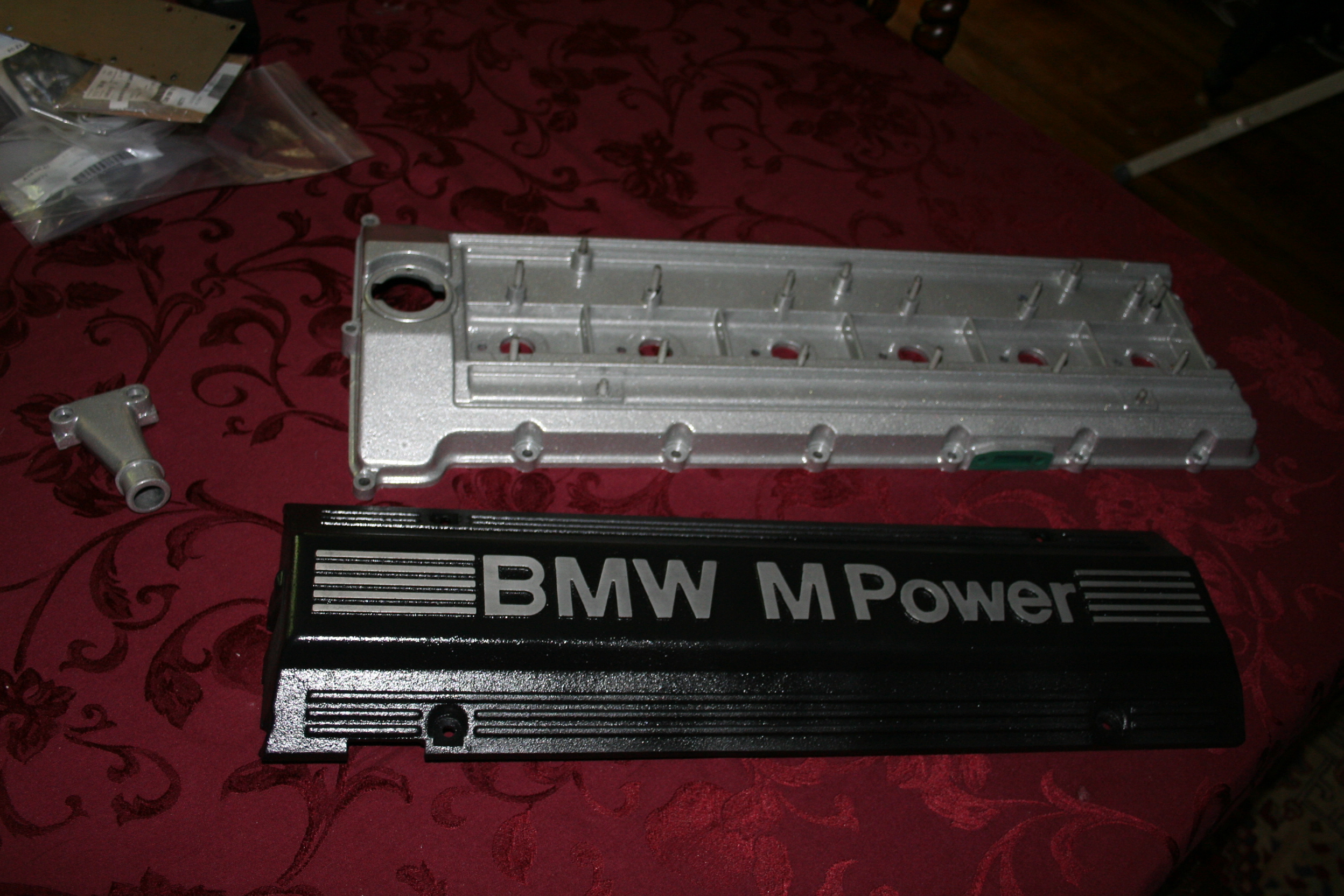
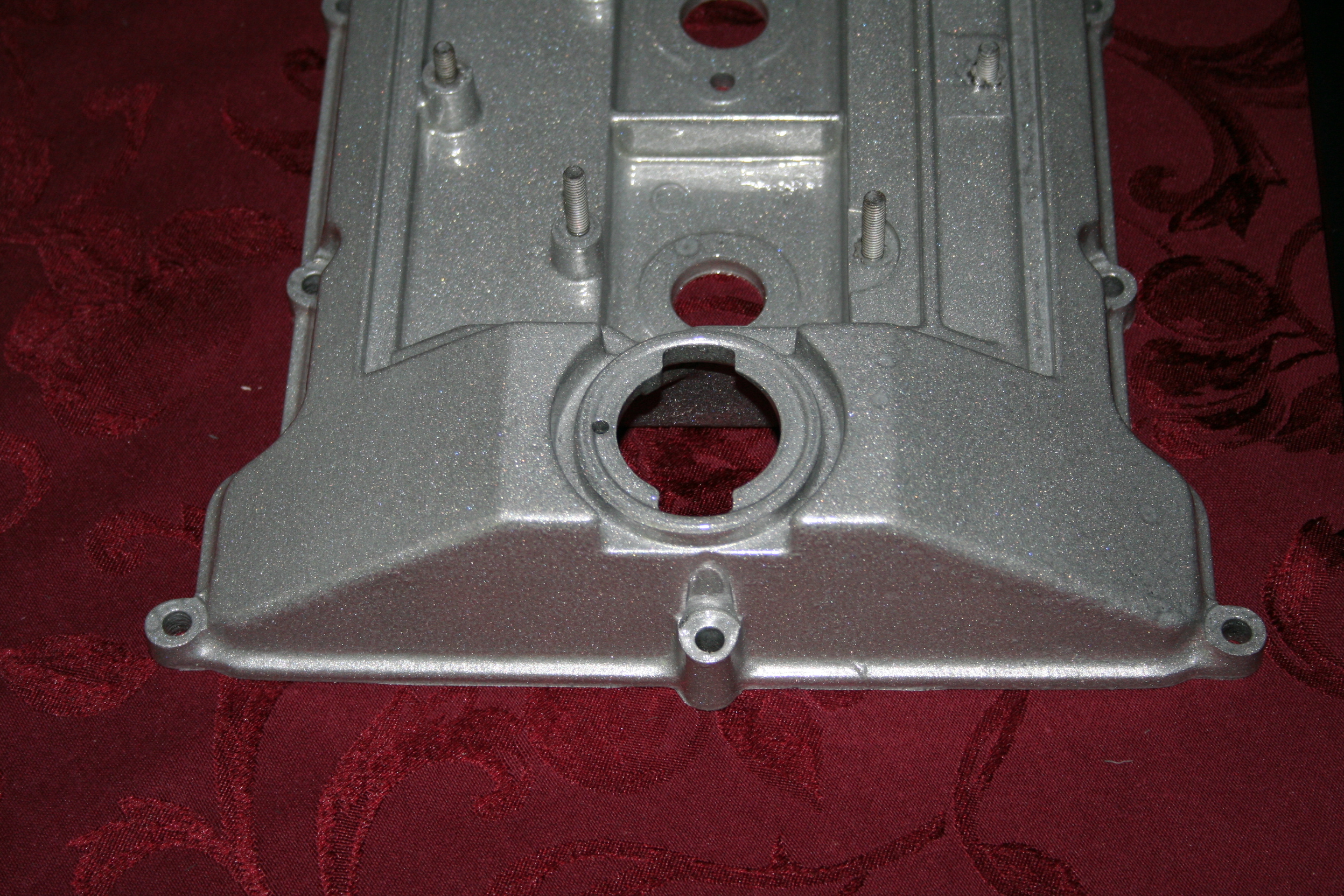
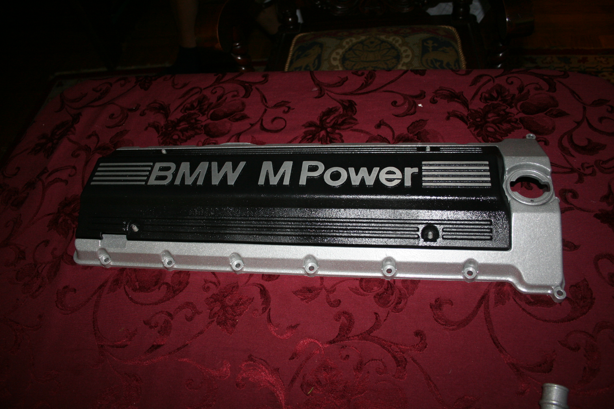
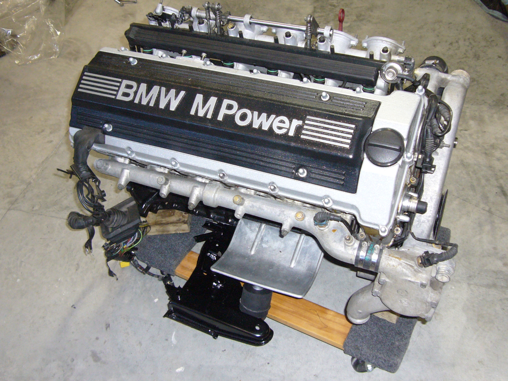
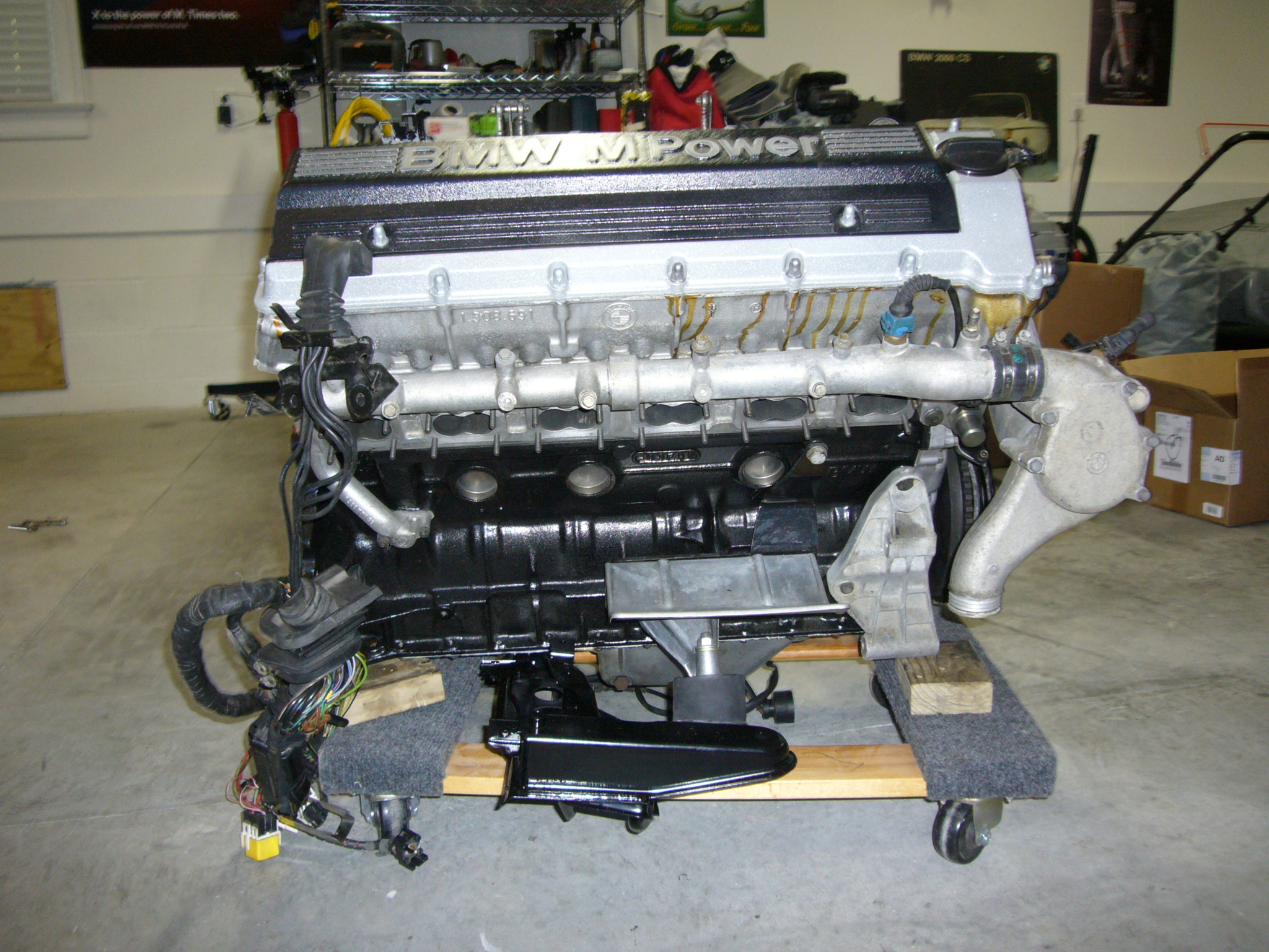
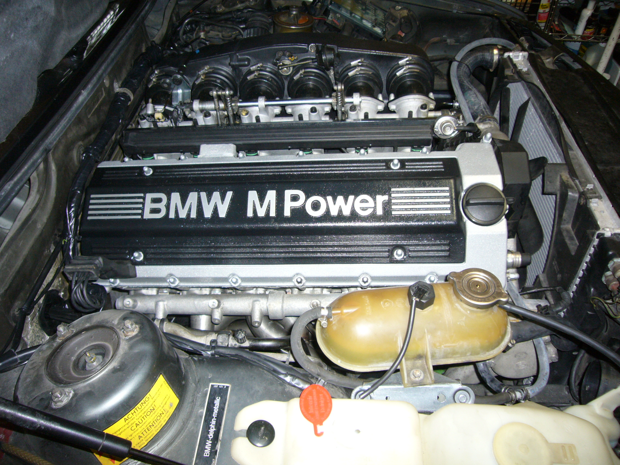
We decided when refurbishing the plenum and the valve cover that we wanted to go with something that looked as close to factory as possible. In order to do this, we had three pieces that we needed to refresh. The valve cover is actually two pieces - the aluminum portion and the inlay that is (we think) Magnesium. We wanted the inlay to match the intake plenum as closely as possible as it is a near-crinkle coat finish. Also there were some gouge marks on the intake from shipping damage. For the valve cover, we were able to get that powder coated. Now, powder coating aluminum is tricky, but doable. The results speak for themselves.
As for the inlay and intake plenum, these were first stripped of that horrible purple paint. Then cleaned thoroughly. And we used a semi-gloss black engine enamel paint to be able to sustain the high temperatures. The problem with this paint is that it's very prone to chipping. And we also added a clear enamel as the final layer. This retains the crinkle finish in the aluminum / magnesium, and gives the closest factory finish. The painting was a long process making sure everything was masked off appropriately and that the paint was given sufficient time to dry.
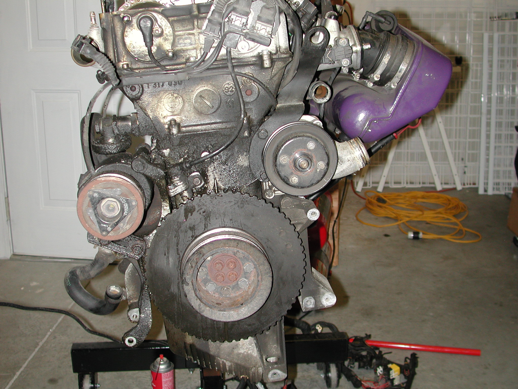
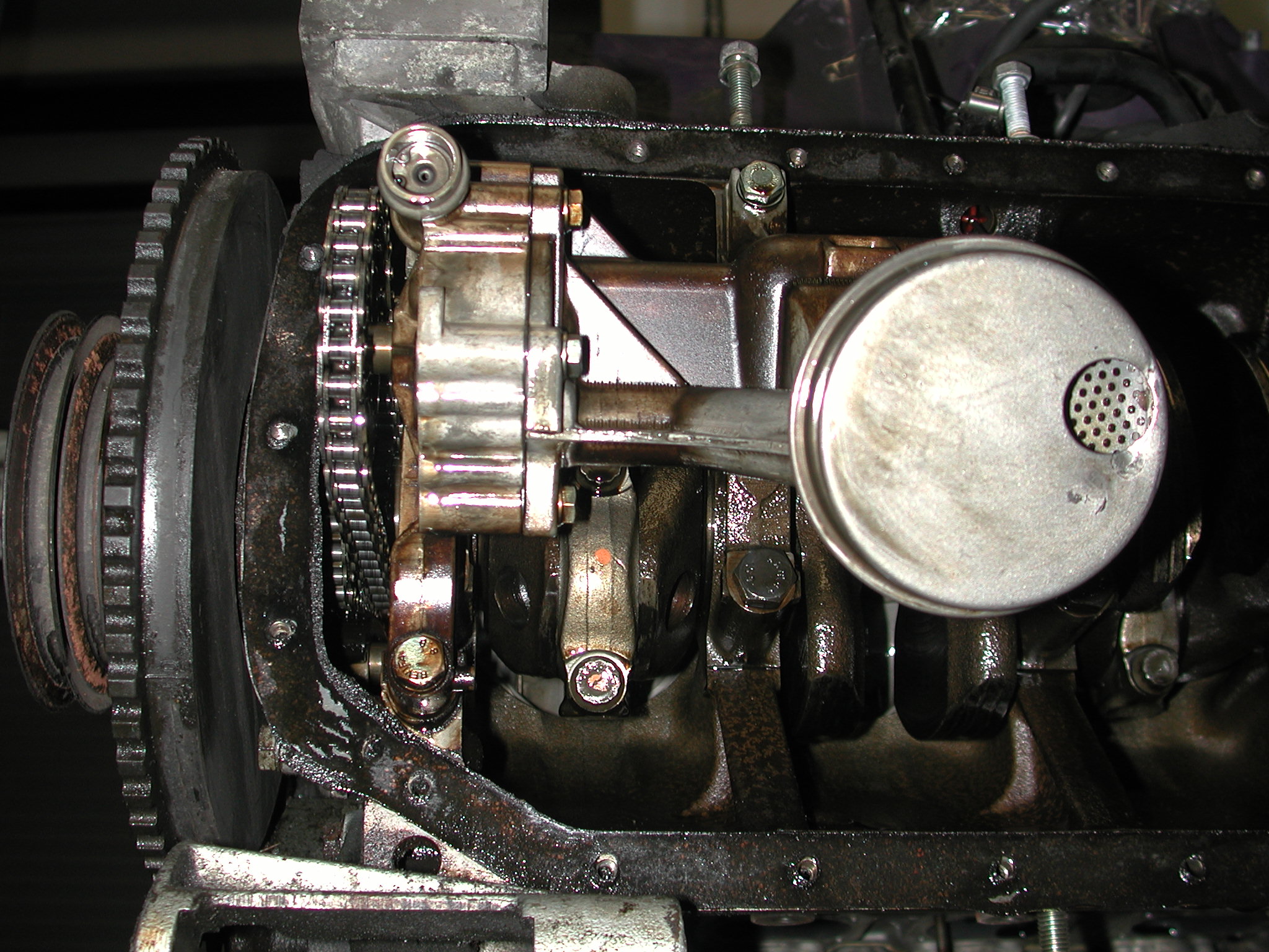
Now my attention moved to the bottom end. First I removed both accessory brackets from the motor. I then remove the accessory pulley and the harmonic damper. The harmonic damper is held on with 4 Torx head bolts that must be replaced. When reinstalling them they also require torque plus angle tightening which is critical to get right.
Once the damper was out of the way I moved my attention to the oil pump. I decided that I wanted to use the E28/E24 oil pan so that I could ensure the proper fitment in the car. I verified this would work by cross referencing the oil pan gasket, which is the same for both motors. The next item that had to be verified oil pump. The B38 oil pump will not fit in the E28/E24 oil pan so I was lucky enough to be able to use an old M88/3 oil pump to verify the fitment. Everything worked great.
I then removed the old B38 oil pump which exposed the bottom end.
C. Refreshing components and partsAfter the oil pump was removed I turned to the rod end bearings. I knew the motor had 67k miles on it, which is generally considered low mileage, but unfortunately the B38s require rod end bearings at this mileage - especially if they are driven hard, but its good piece of mind even otherwise. Since I was already in there I decided to replace them. This was not a big deal especially since the mileage on the motor was so low. I was able to use OE bearings as the wear on the journals was insignificant. One key point is that the rod end bolts need to be replaced and are tightened to torque plus angle. Also make sure to use assembly lubricant when reassembling the bearings. This will help prevent scoring and spinning a bearing when doing the initial start-up of the motor. Also it is required that you add an oil pump support bracket (for use with the E28 oil pump) onto one of the crank main bearing caps. I purchased a new bracket from BMW and new bolts and installed this so that the back of the pump could be supported.
Now I moved my attention to the timing chain and tensioner. I decided that since I was in the motor I would replace the tensioners, guides, and chains. To do this I first had to pull the water pump off and should be replaced anyway. Now that the water pump is out of the way you can get access to all of the lower cover bolts. I then set the crank and cams to TDC and removed the tensioner. Now if you read the factory manual it states that you must remove the head to ensure that you get a good seal between the head and the front lower cover. I have never had to remove the head, I have just been very careful when removing the lower cover not to damage the head gasket. This worked and I was able to get access to the lower portion of the chain.
I then pulled the cam gear covers off and unbolted the gears and the upper chain guide. This allowed me to drop the chain down out of the top of the head. I had to remove the chain guide on the intake side of the motor which was fairly easy. I then had to remove the tensioner guide. This was very difficult. The tensioner guide is a two piece item. The top section in the head is easy to remove. The lower section is much harder to remove. The part is on a stud at the bottom of the block and the top is located in the head. There is not enough clearance in the head to pull this out. I found a way to get this part out by brut force.
Once all the timing chain equipement was removed, I started the reinstallation. The most difficult part of this was the lower tensioner guide. I was able to get everything reinstalled and tightened to spec. I decided to use the S50 tensioner upgrade as I have seen problems with the old style tensioners. I then verified the chains were set right by rotating the motor by hand and verifying all the timing marks. This is critical because the worst thing you could do is be off 1 tooth. I also installed the oil pump chain and tensioner.
Now that the front lower cover was installed, I moved my attention to the back of the motor. The rear main seal and main seal cover gasket were replaced. I also installed a new pilot bearing in the crank. My attention then moved to the back of the cam tray cover, which I replaced the gasket. I also replaced the gasket and O-ring on the oil drain from the heads back to the crank case on the back right corner of the motor.
With all of the block covers refreshed I could now put the oil pan back on. I used the E28/E24 oil pan and gasket as stated before. I also put some attention on the accessory brackets and oil filter housing. I wanted/needed to change the accessory brackets because of the use of the E28/E24 oil pan and also the determination that I did not want the exhaust air pump system. On the passenger side of the motor I used the standard E28/E24 AC accessory bracket. This part is a bolt on, but I had to wait to ensure that the AC compressor pulley lines up with the crank pulleys. On the driver's side I had to use the E28/E24 accessory bracket as the E28/E24 oil pan has no mounts for the power steering pump. This bracket is also a bolt on and the best part about using this part is that the power steering pump and the 90 amp E28/E24 alternator line up with the crank pulleys.
Now that I have the accessory brackets and oil pan on that I wanted to use, I turned my attention to the motor mounts. I knew I could not use the B38 engine mounting arms because they do not line up to the mounting points on the front subframe. I decided that instead of making my own adapters, I would get Koala Motorsports adapters. On the passenger side of the motor everything worked easily. I painted the bracket to match the block and mounted an M88/3 engine mounting arm with heat sheild. The reason for this is that I knew I was going to use the M88/3 headers and I wanted to ensure clearance. On the driver's side things are more complicated. First off the bracket must be machined to clear the intake support bracket. The intake bracket must also be modified to clear the bracket. Once everything was test fitted I painted the brackets to match the block and installed them and the E28/E24 driver's side engine mounting arm. Don't forget the bracket for the oil level sending unit.
Once the engine mounting arms were installed it was time to move onto the oil filter housing. A lot of B36 and B38 conversion I have seen have used the B38 filter housing which is top mount like the E34/E32 M30s. The problem that I have with this that the connection to the E28 M5 oil cooler setup in my car would need to be modified and this would be a lot of work as I would have to either estimate what needed to be done, or trailer the car to a shop for it to modify the connections to make this work. This all being said I decided to use the E28/E24 M car setup. Now I ran into a small issue when installing this with the motor mount adapter bracket. One of the bolts for the adapter bracket sits directly under the oil filter housing. I had to modify this bolt so what I did was take a grade 10.9 bolt and shave the head down by 50% so that it cleared the oil filter housing. This worked really well. There is about 2mm of clearance but as everything is solid mounted I am not worried about it.
Next I reinstalled the starter motor which was previously removed to allow for painting the block. I am using the B38 starter motor. On the B38 motor there is a separate wiring harness to connect the alternator and starter together. In this sub-harness there is also the connector for the charge light indicator. This sub-harness has a metal tube in which it is housed. What I found was that using the E28/E24 M filter housing causes an interfierence with the metal tube. I had to cut the tube short while being very careful not to damage the wiring as you cannot remove the wiring. Once this was complete I was able to mount the tube to the motor and wire up the starter.
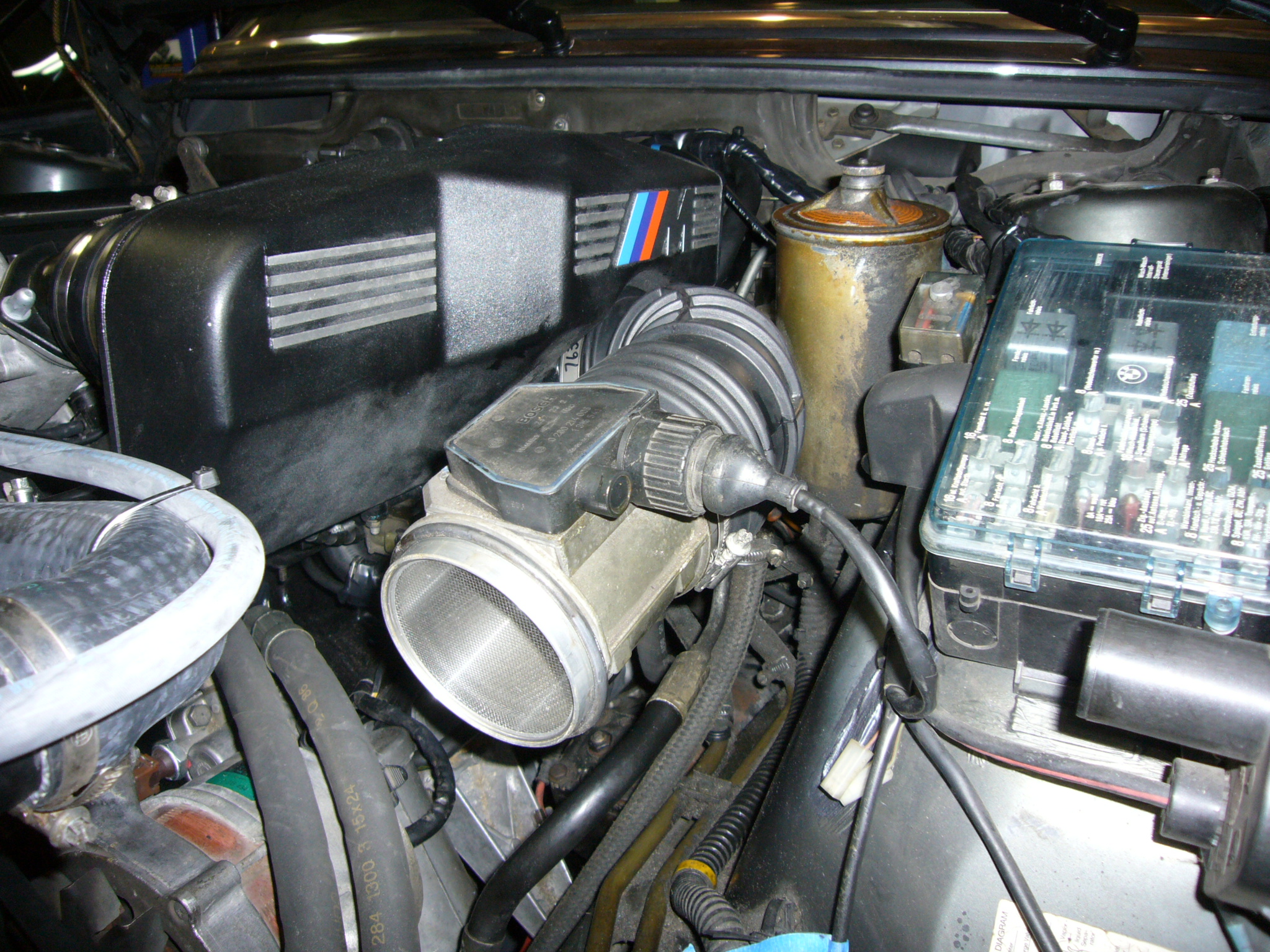
I decided at this point it was time to move to the throttle bodies. Now with such low mileage on the motor I decided a full rebuild of the throttle bodies was not required. Instead I decided that I should clean everything and put new O-rings in for the idle air bypass and between the throttles and head. The 3.8L does not use gaskets between the throttles and the head. Now unlike the M88/early S38s the B38 and I believe the B36 use an air distribution rail with anti-backflow valves. I replaced all the seals on these to make sure I don't have vacuum leaks. I also replaced the O-rings in between the throttles and head. Also one key is that you need to use the S38 B35 throttle actuation lever. The reason for this is that you can then use the E28 M5 throttle cable and brackets. I also checked the measurements of the throttle plate openings. These were off so I put them back to factory baseline. Now of course this means that the throttles will need to be balanced once everything is up and running, but honestly it is a whole lot easier to do now. I almost forgot, when removing the throttle bodies the harness came with it. I also replaced the fuel pressure regulator as it looked to have been damaged during shipping. When I reinstalled the throttle bodies I put the harness back on.
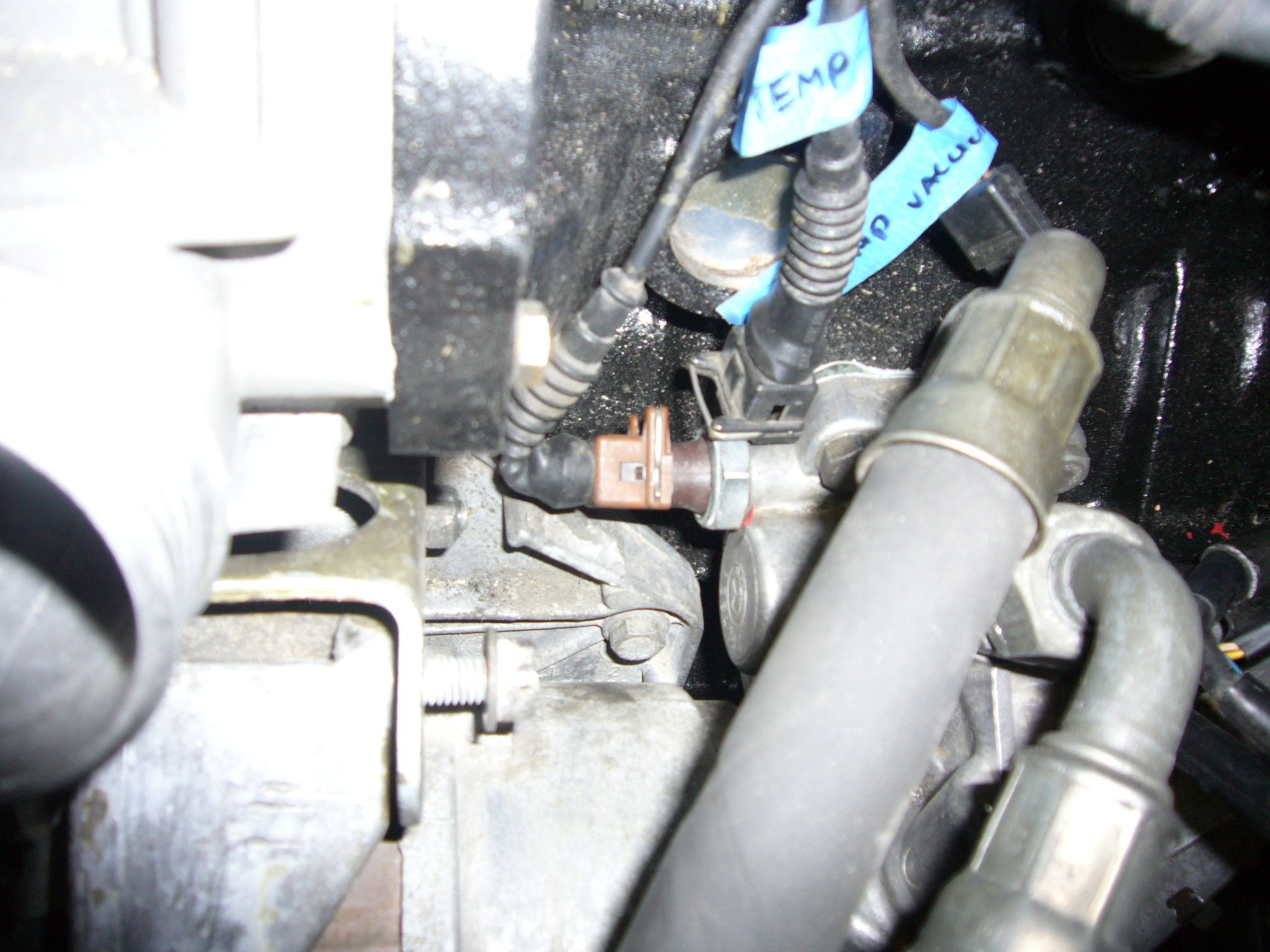
With the throttle bodies mounted and set I was able to turn my attention to the idle air system. This just needed cleaing and some new o-rings and rubber pieces. All of this was reinstalled and I moved onto the vacuum control side of things. I removed all of the air pump control items and replumbed the vacuum lines that control the resonance flap in the intake. I also used the vacuum port on closest to the firewall for the vacuum required for the interior temp sensor.
I then moved to the water pump. As I stated before I removed it and so now was the time to reinstall. Once that was on I moved my attention to the coolant cross tubes. I took them completely apart and put in a new thermostat along with gaskets. The cross tubes were ready to go back on, but first I need to reinstall the harmonic damper. The harmonic damper on the B38 is different than that of all the other S38s. The damper uses 4 very long torques bolts to hold it in place. This is different that the other S38s which use a 36mm nut. The key with these 4 bolts is they are one time use and are torque plus angle. The key here is you must lock the motor in place to the crank does not rotate while tightening. This is easily done with a bolt and prybar with a spare flywheel. Once the damper is mounted then the crank position sensor can be placed. It is also critical that the spacing for the sensor off the teeth is correct. I also then installed the cam position sensor in the cam gear cover and connected the wiring for these sensors back to the engine harness. At this point I decided not to reinstall the cross tube so I could have plenty of clearance for the front of the motor during installation. I did however install the accessory pulley which is also different than any other S38. The B38 accessory pulley has 3 v-belt drives instead of 2. The reason for this is that the harmonic damper for the S38 does not have a V-belt drive.
The valve cover was also reinstalled at this point with new gaskets. It was critical that the valve cover did not get scratched during installation, but I felt it was more important that no dirt got in the motor so it was installed. The water pump pulley was installed and then the motor was "ready" for the swap process!
4. Installation
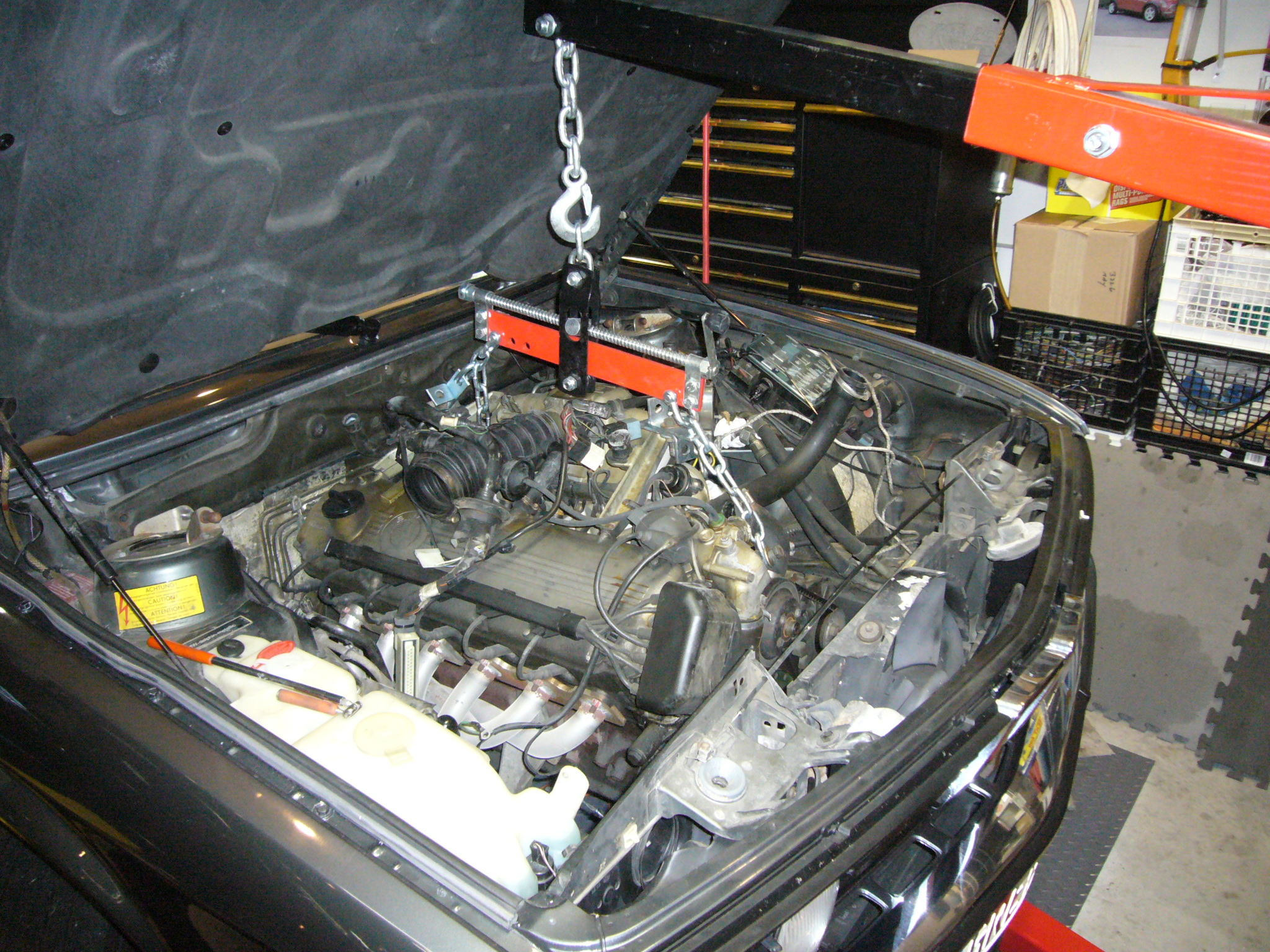
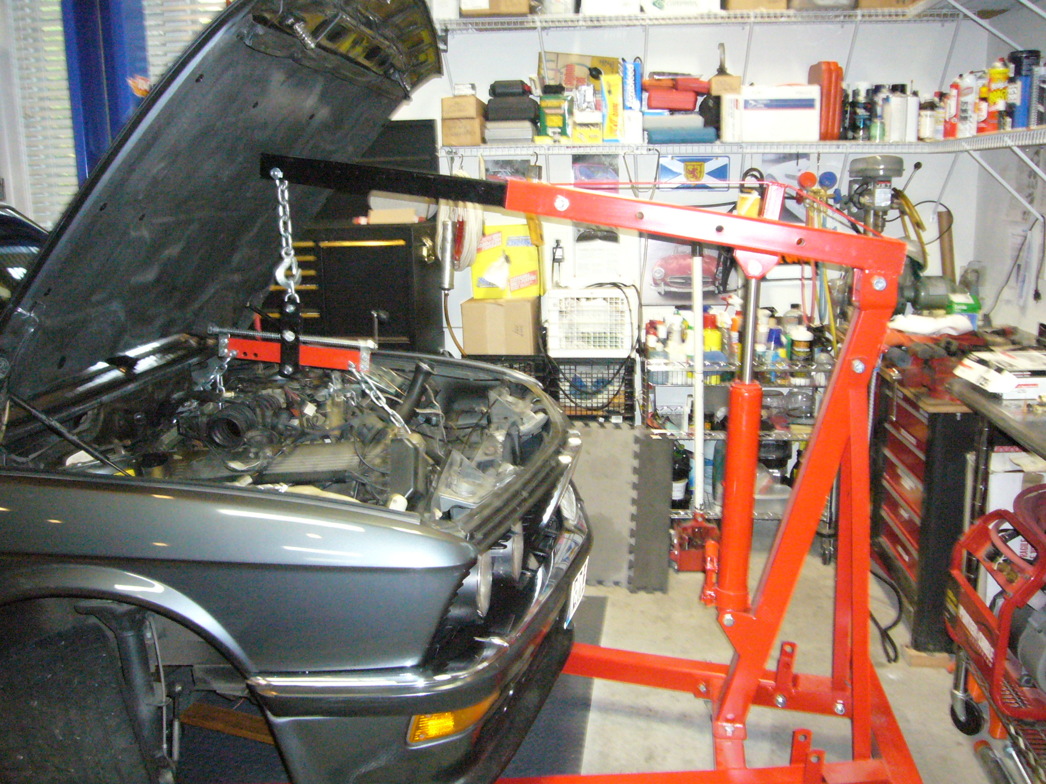
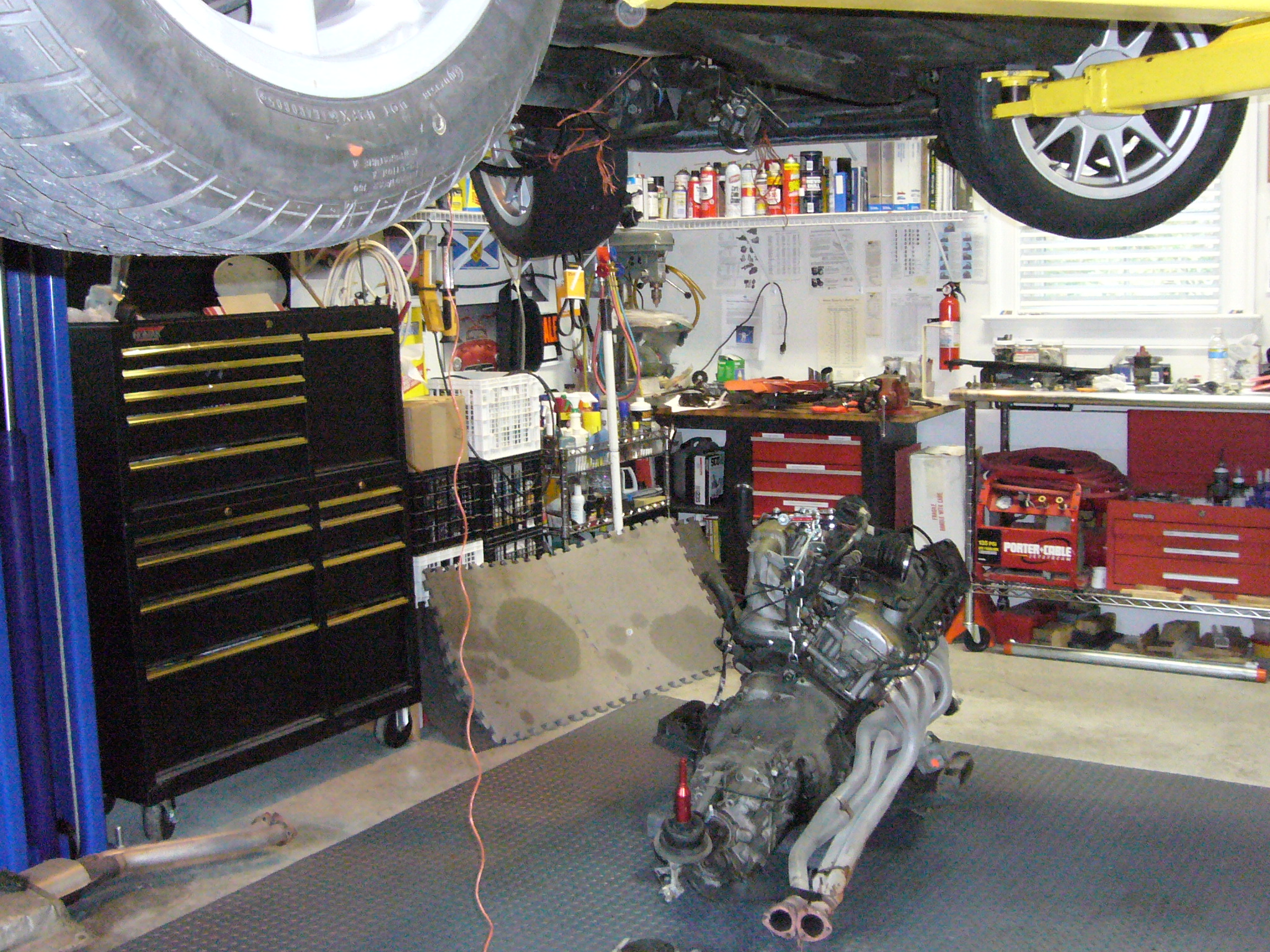
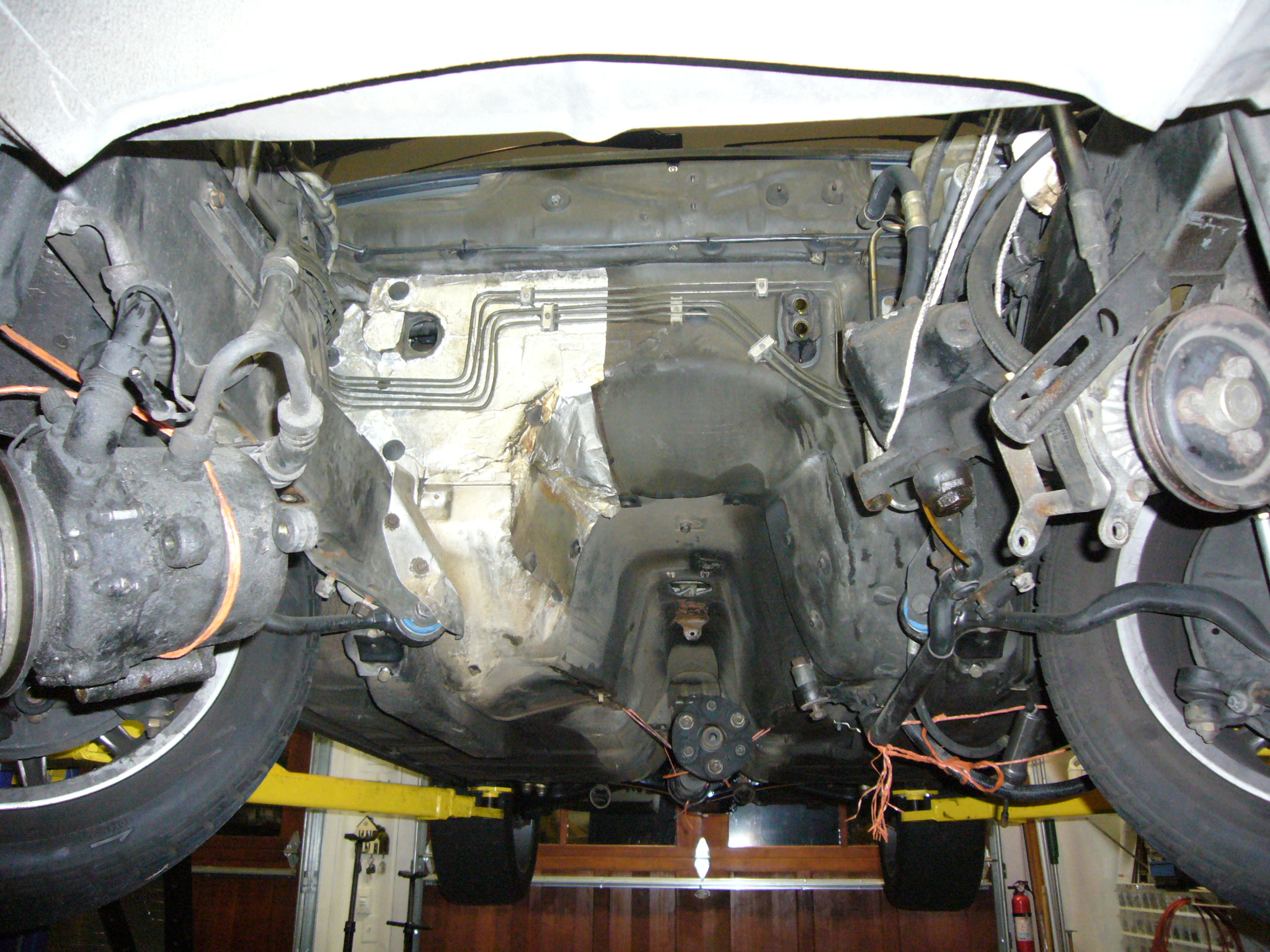
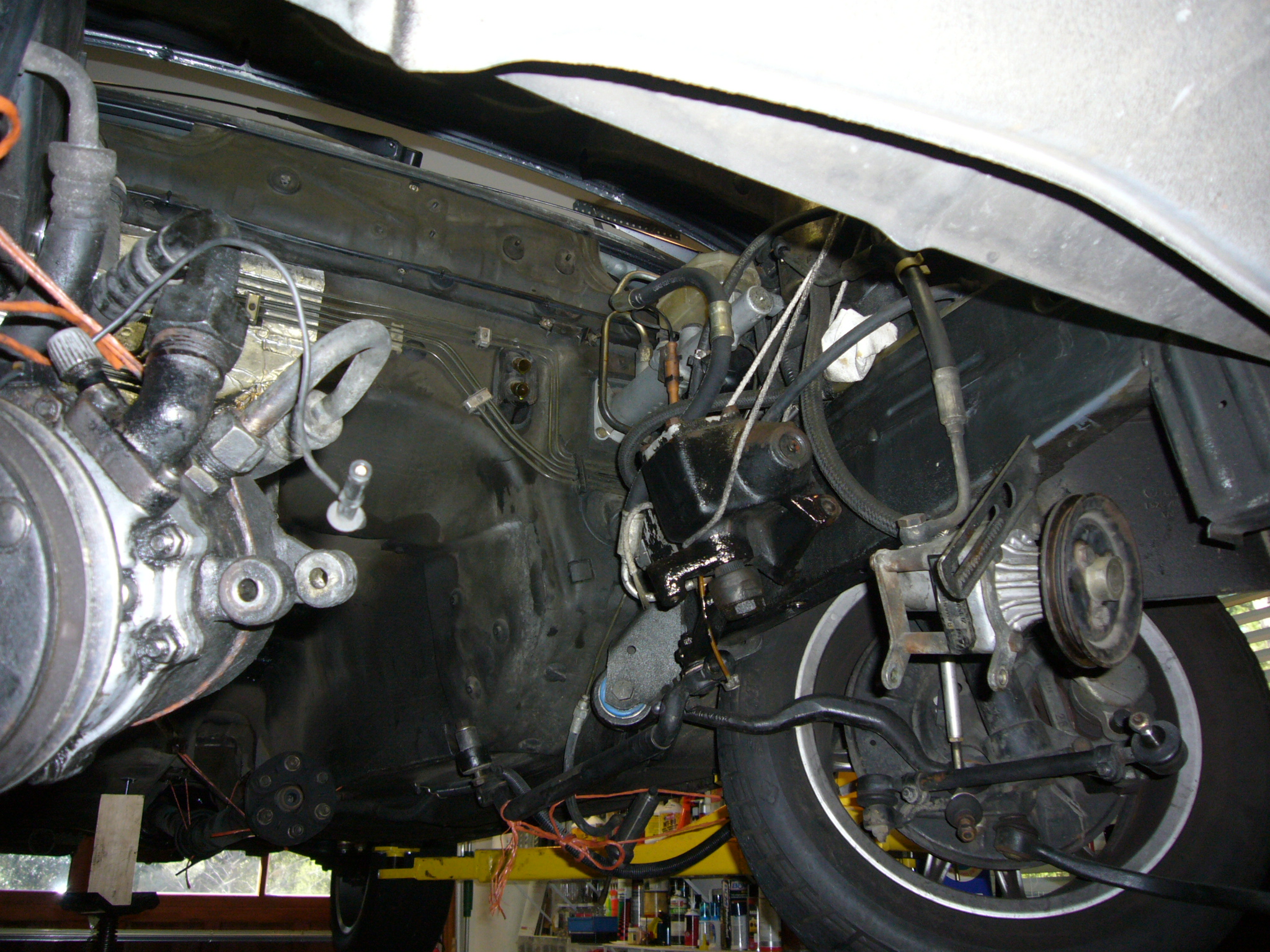
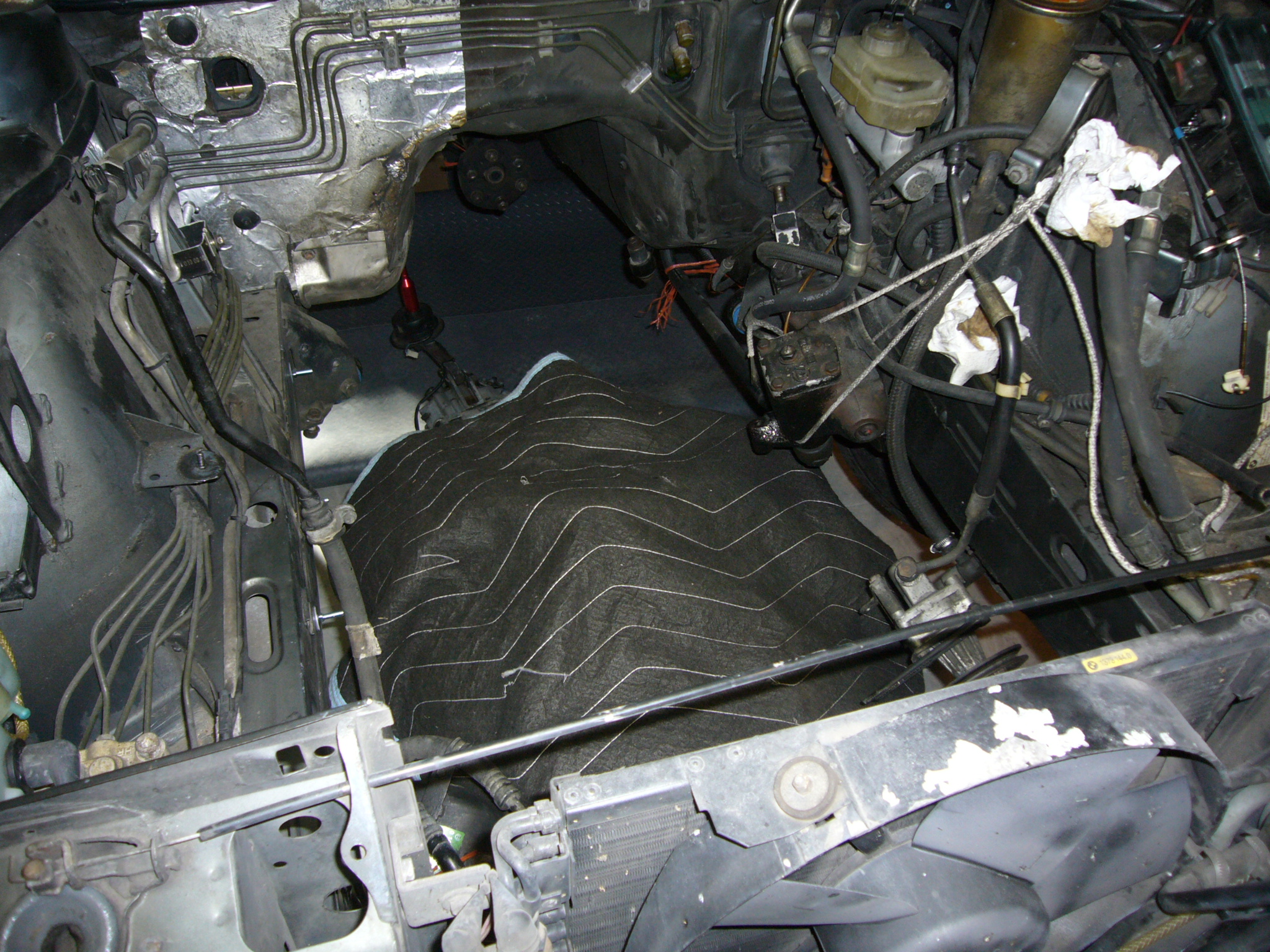
A. Removal of old motor and engine bay preparationI don't think we need to go into much detail about the old engine removal because I think this is something that is covered in many other places. One note is that I never pull the engine out from the top. I always drop it from the bottom and if the correct prep work is done you don't have to remove the AC compressor, Power Steering Pump or steering box from the car. This saves a lot of time having to deal with the fluids from these systems and getting them back up and running when you are trying to make sure the motor is functioning correctly. Anyway here we are with some pictures.
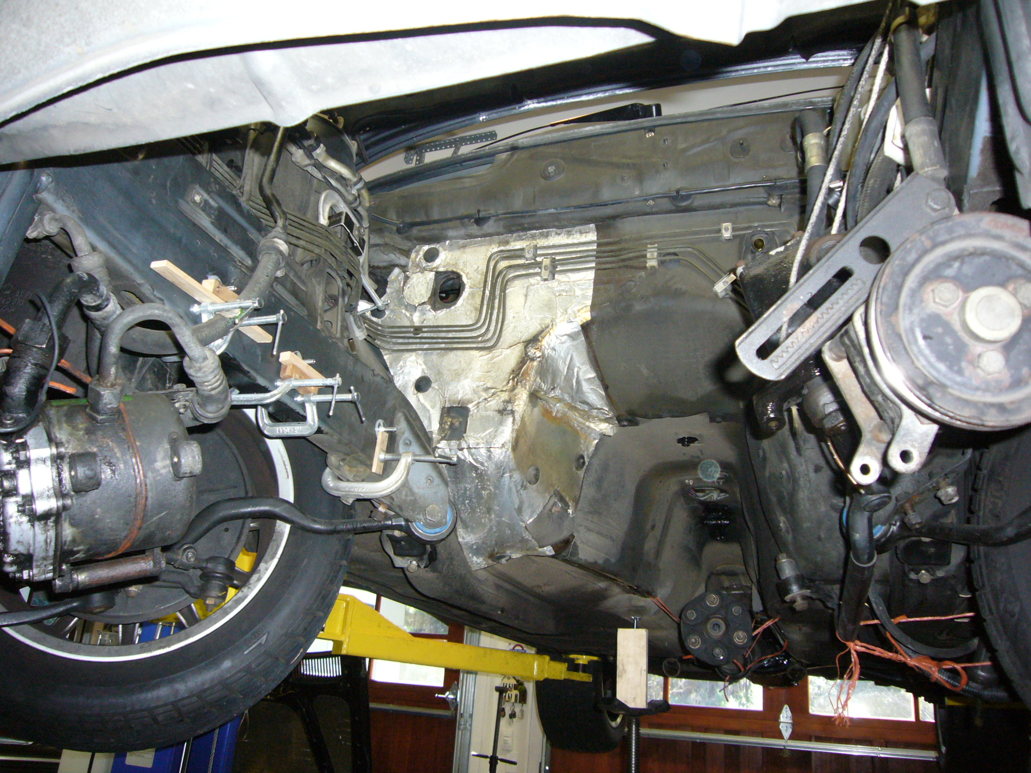
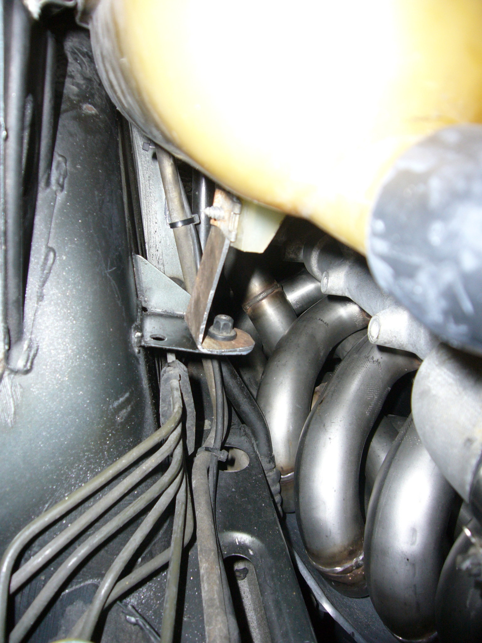
Once the old motor and transmission is removed, we prepared the mounting tabs and studs for the heat shield on the passenger side frame rail. The E28 M5 comes with a heat shield here, and it's relatively simple to mock up the heat shield with the studs. We used studs that came with a flat plate from McMaster, and epoxied them to the frame rail.
We suggest installing the heat shield because of the heat that the exhaust headers will generate. Protecting the AC lines and brake lines is critical in this area.
ii. Battery and rewiring
Unfortunately this topic is a little out of sequence and hence forth I don't have pictures. I did the battery relocation and prep a long time ago, approximately 5 years ago. I did this at the time because I wanted the weight balance improvement and I also knew at some day I was going to install an S38. So I purchased a battery box out of a wrecked M5 and got the cables and power distribution blocks along with all the trunk carpeting. This was great because then I could get the trunk to look like a factory M5. I started with the battery box. The placement of this is a little tricky because the M5 has a different supporting brace that runs down the side of the trunk on the passenger side. This meant that I had to do some work to get the box in the correct place. Once I determined the position for the box front to back in the car, I then marked the supporting brace. I then cut the supporting brace and was able to actually use it to surround the box. This was really critical because I did not feel like removing the gas tank to weld the box in, so I epoxied the box to the trunk floor and then was able to bolt the box to the supporting brace. This provided me the ground that is needed so that I can use all the factory items. It also provided a lot of strength for the box and honestly the box is not going anywhere.
Next I moved on to running the lines. I first ran the cables from the trunk to under the rear seat. At this point the main cable runs across to the driver's side of the car and the ECU power supply runs down the passenger side. Both cable run down the transmission tunnel if I recall. Once the main cable is under the driver's seat it splits. The main cable goes through a punch out in the floor pan. If you are careful you can remove the punch out in the floor without damaging the shape of the floor and all you have to then do is paint the edges and install the grommet. Now there is a plastic cover that protects the cable as it comes out of the floor. This piece is NLA, I am lucky enough that I have one. I was able to use the same studs as shown in the previous section to mount this cover to the floor of the car. This works out great. Now the next thing is I was able to use the studs for the O2 sensor cover to be able to mount the factory clamps and hold not only the cable but also the O2 sensor wire to the floor. This worked out great. I then connected the cable to the starter and removed the old 535i positive power lead.
Now moving back to the interior. I left the ECU power supply disconnected in the glove box. I did not connect it to the battery as this was something I knew I would need later, but I didn't want to have to tear apart the interior to install it when I had to have it. On the driver's side the wire that comes off the splice is specifically for the power distribution block which is bolted to the A-pillar under the dash. This point is designed to provide power for the Fuse Box and the ABS brain. With this being said I had to do a bit of rewiring. As anyone with a 535i knows there are a bunch of wires on connected to the positive post of the battery. One of those is the fuse box power supply, which must be taken back into the fuse box, and a new line installed and run to the inside of the car. Same thing with the ABS supply. The last one is the power supply for the main relay for the engine harness. This I decided to run back to the lug on the starter. Now I know this isn't correct but this was temporary as the new motor would not need this.
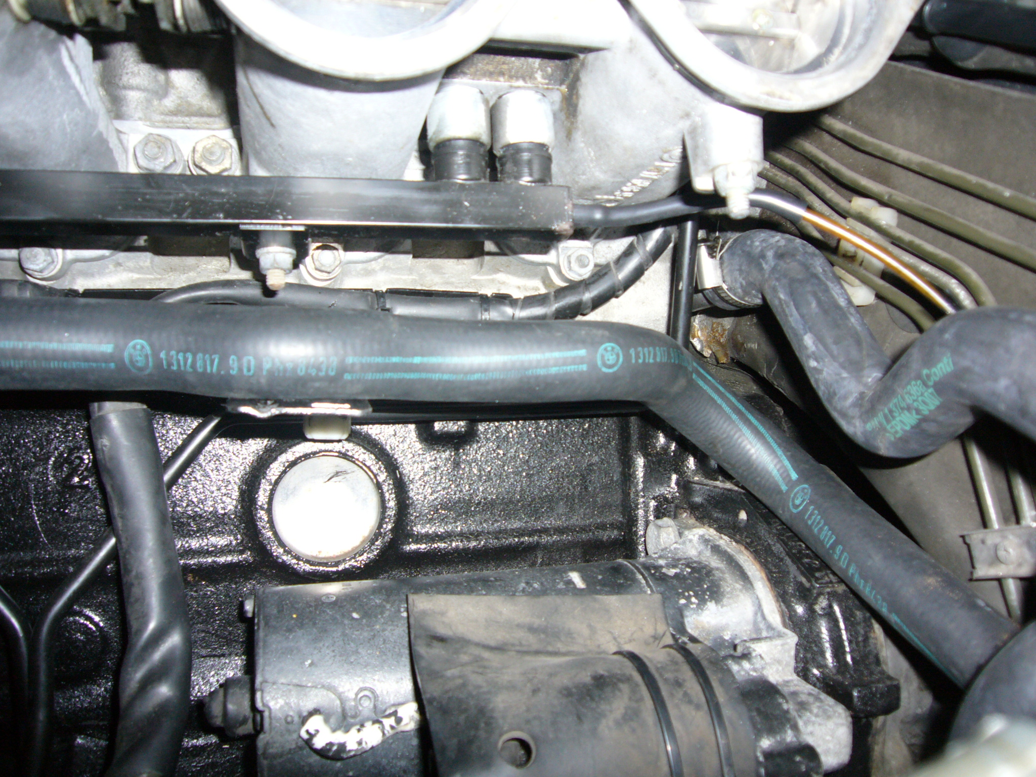
iii. B38 coolant pipes
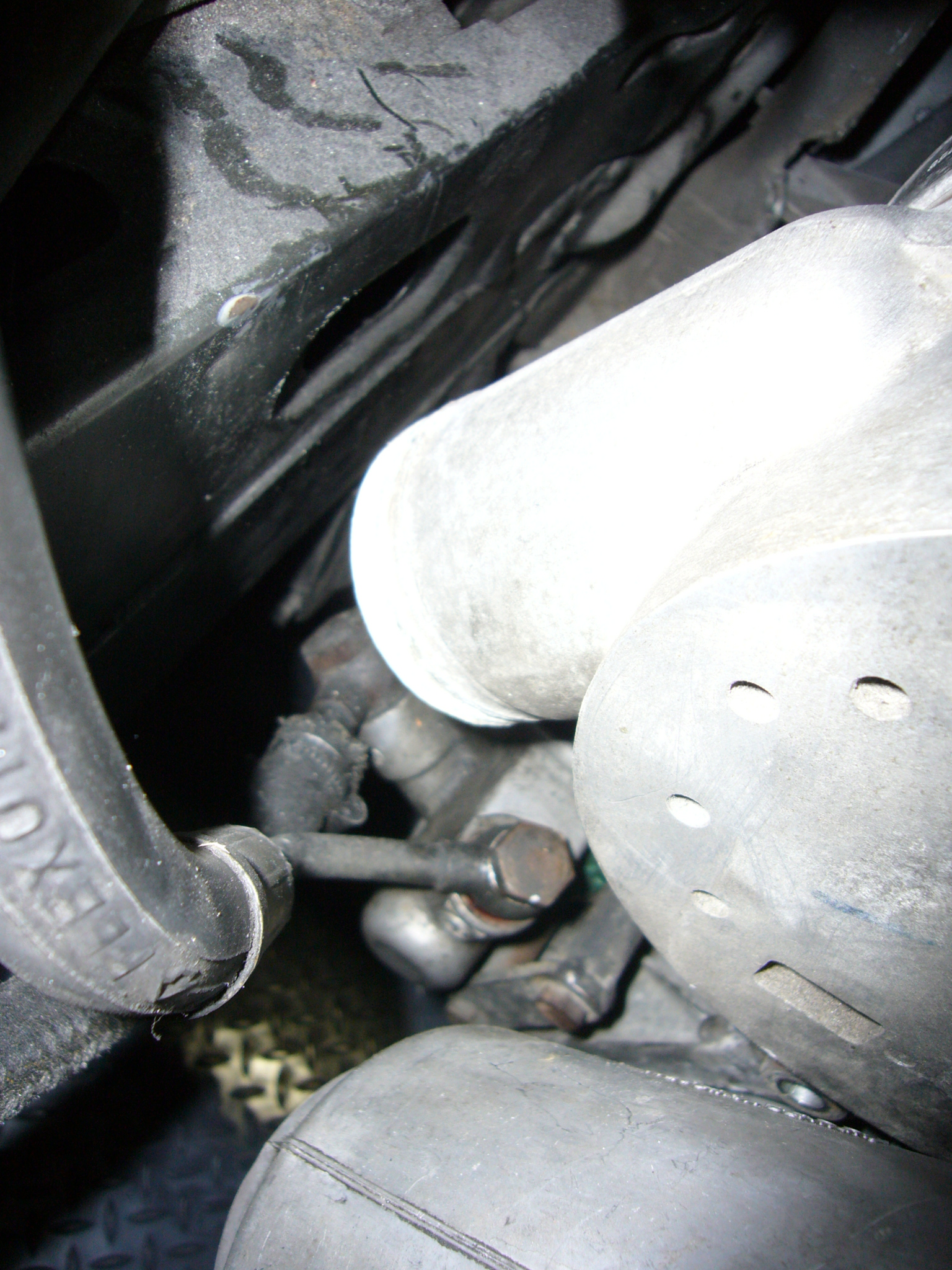
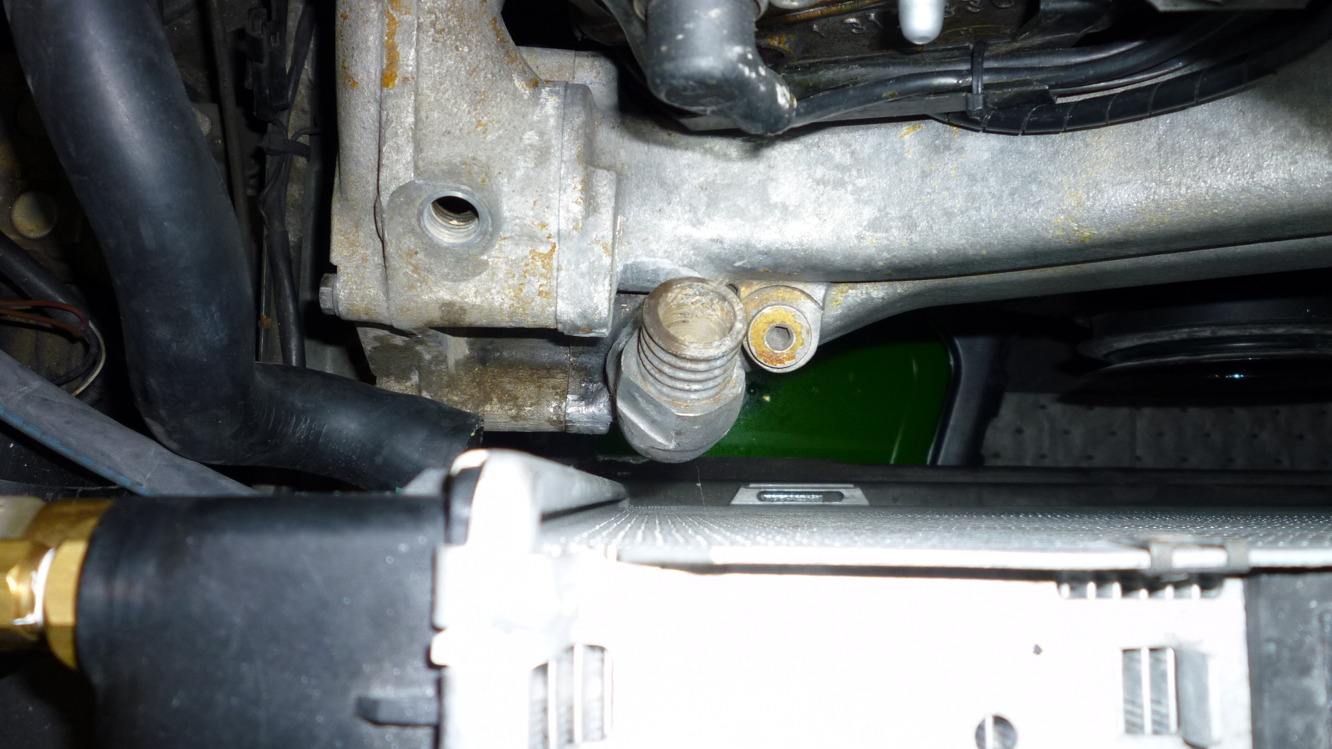
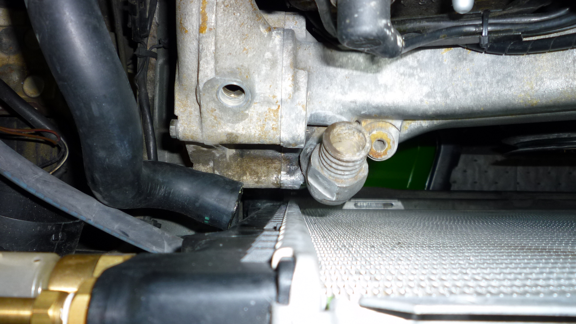
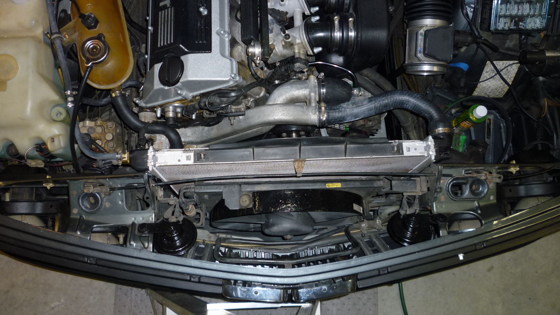
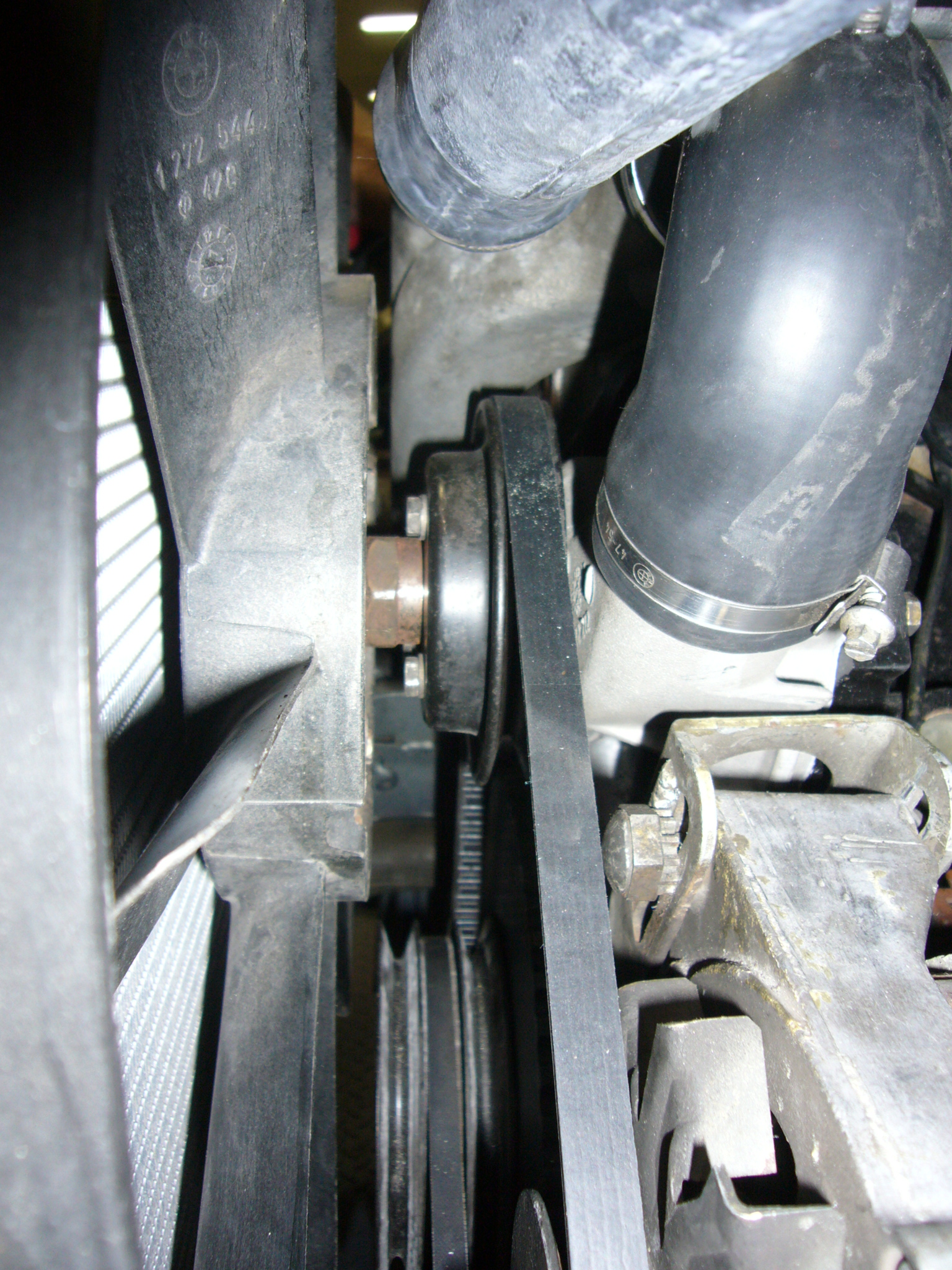
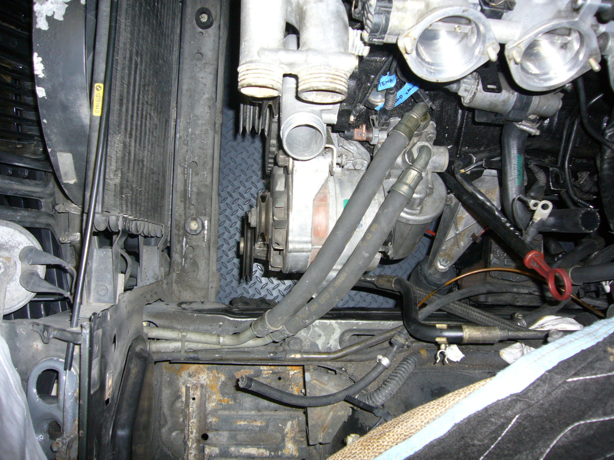
When we were test fitting the motor, we found that the radiator to coolant pipe clearance was very tight to the radiator. In fact, it was hitting the radiator side tank. The radiator core support has a flange that we bent back in order to pull the radiator closer to the core support. This helped, but only marginally.
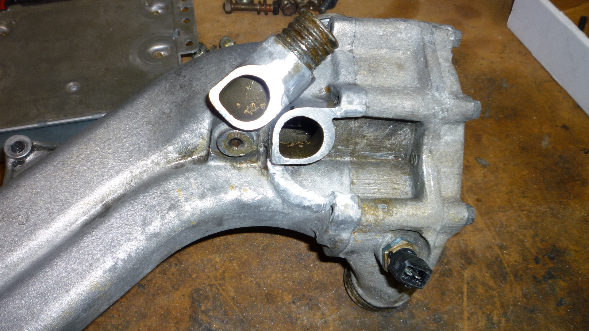
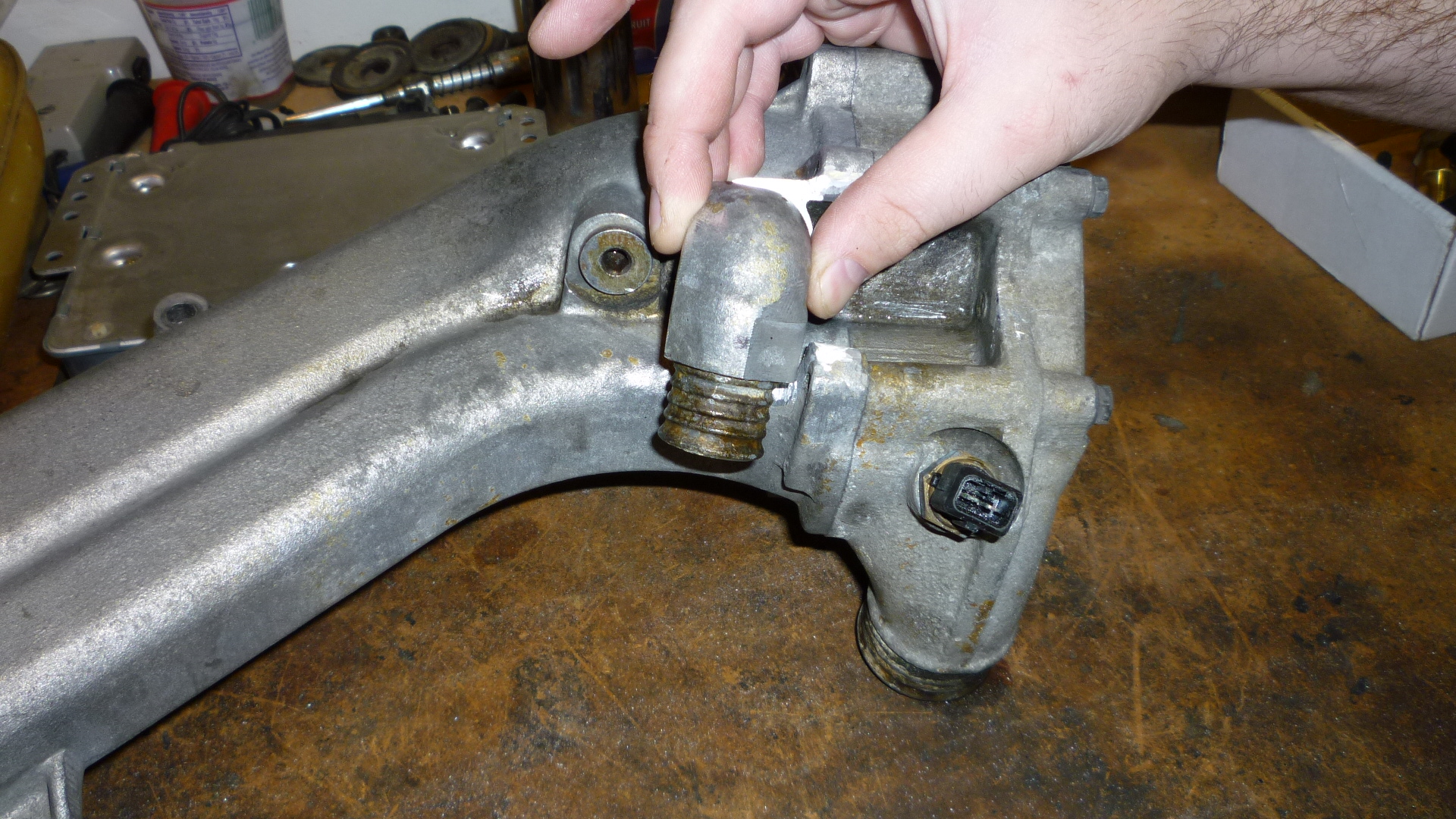
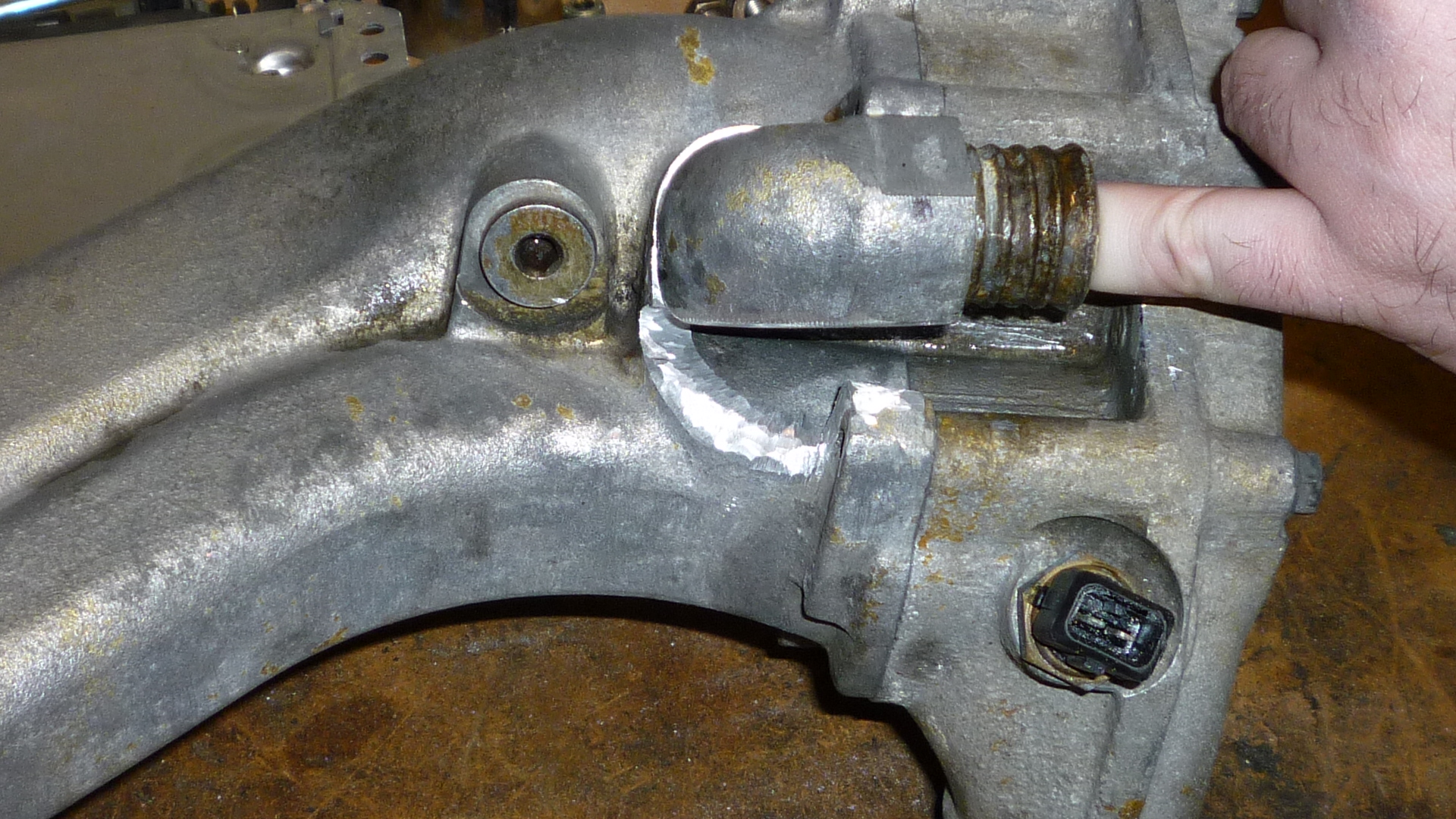
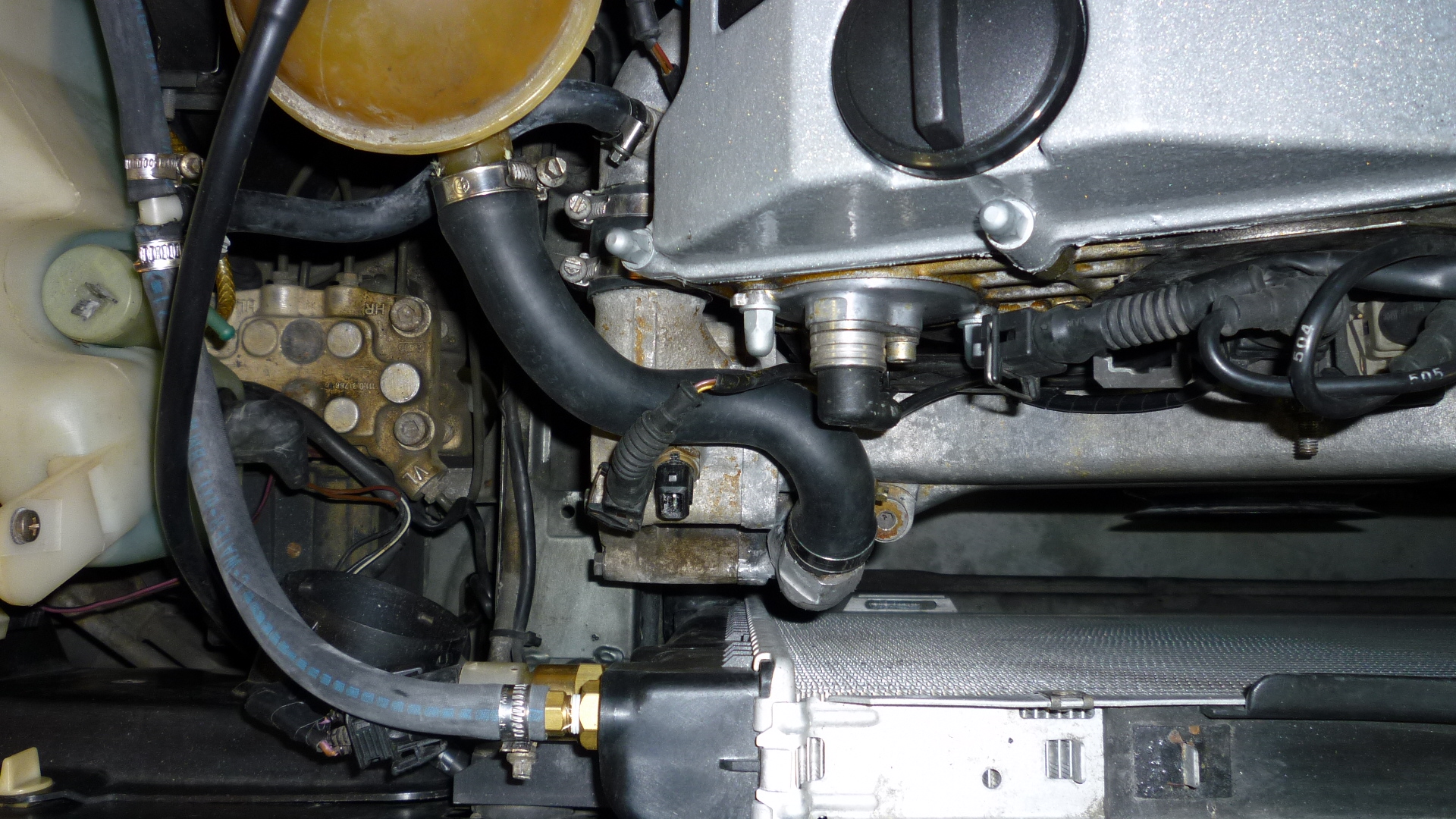
In addition, we later modified the coolant pipes so that the supply bib comes from the top, not in front and to the side. Doing this allowed us to have clearance of about 1/2 to 5/8 of an inch to the radiator with the radiator in its original position.
In addition, the coolant pipe that goes to the lower rad hose only has about 1/4 to 3/8 of an inch clearance to the side of the frame rail. This is acceptable, given the amount of movement side-to-side that this motor has. The bigger concern is the front/back movement.
Also, one other item is that the E28 535i fan shroud has to be modified to fit. You have to cut a rectangular clearance opening on the passenger side of the car so it will allow you to install it. If you don't it'll contact the aluminum coolant pipes.
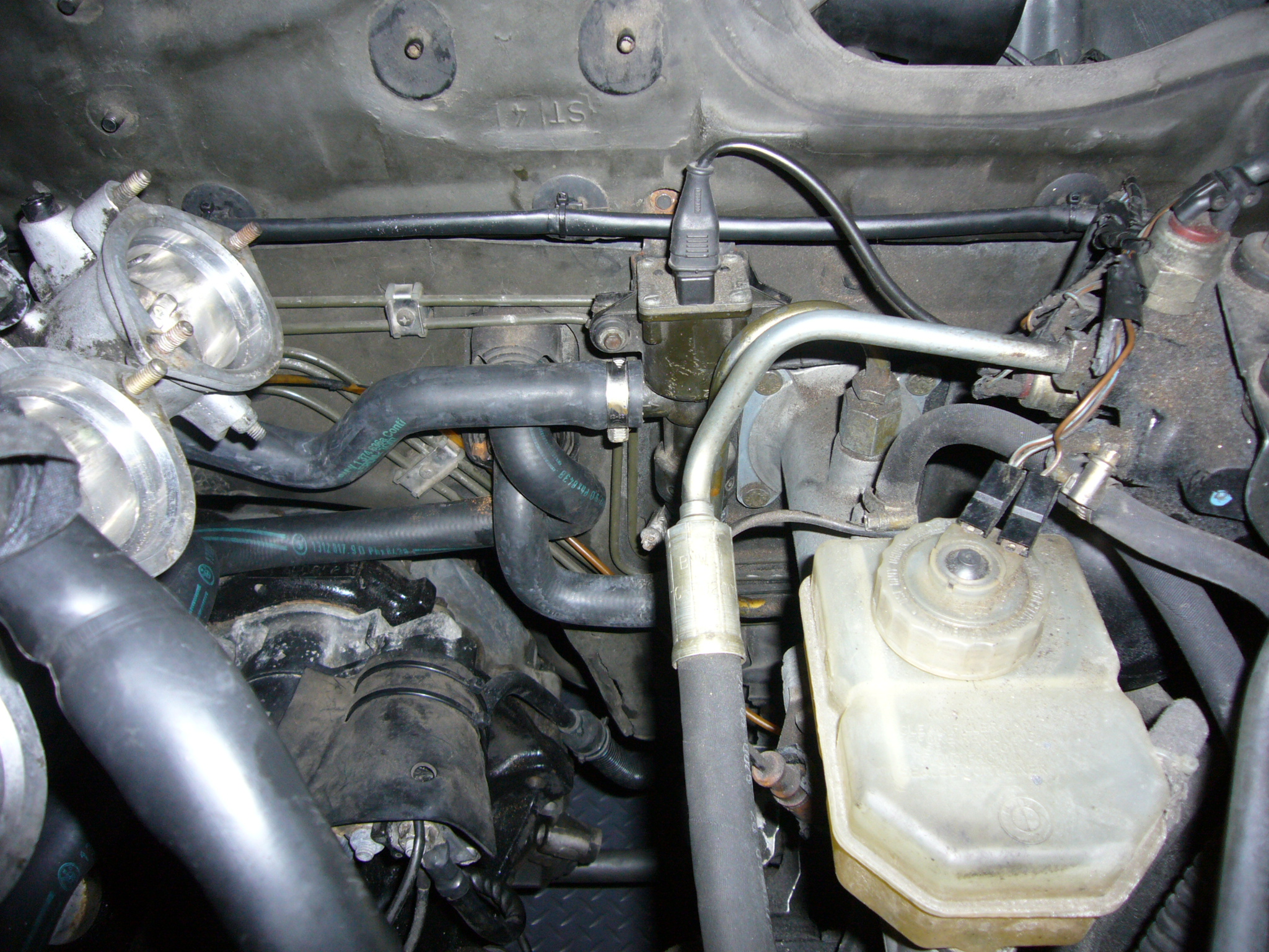
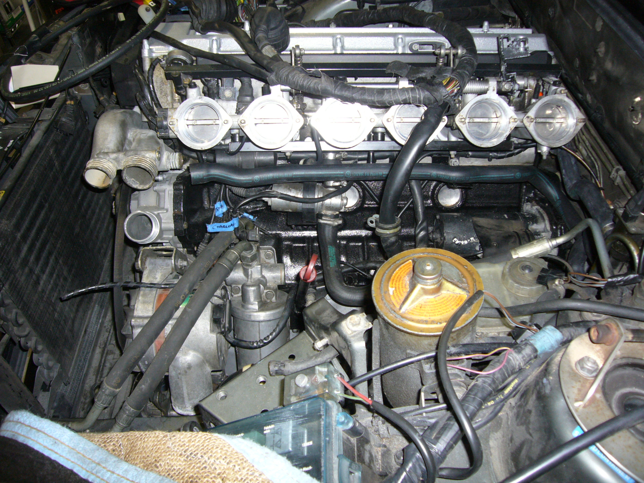
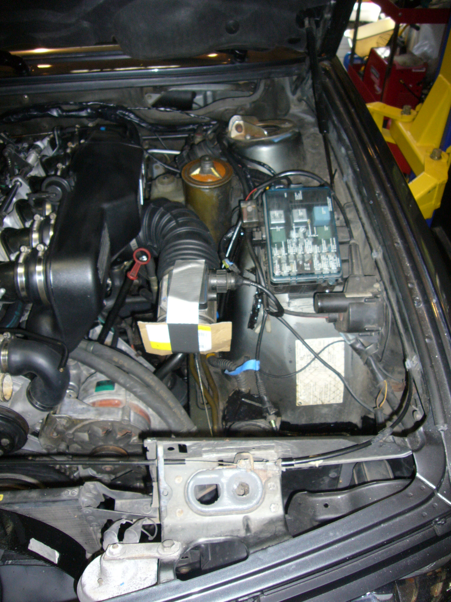
iv. Removal of engine bay brackets to clear intake
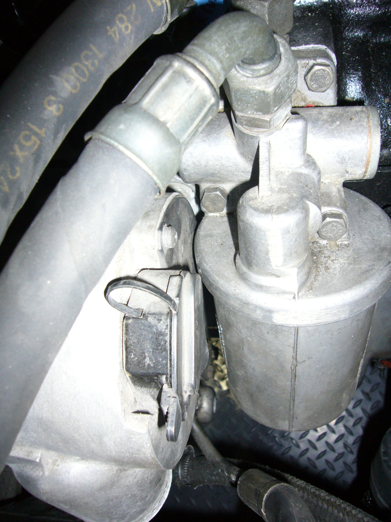
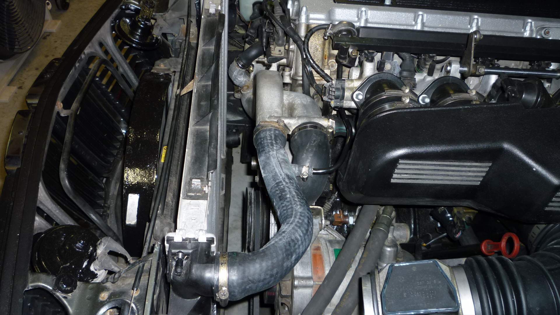
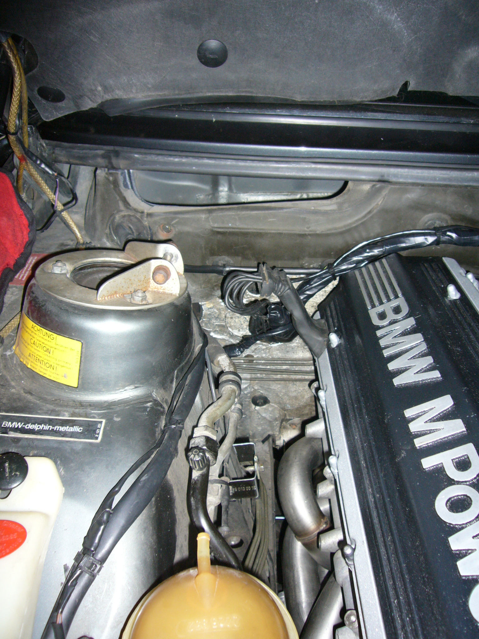
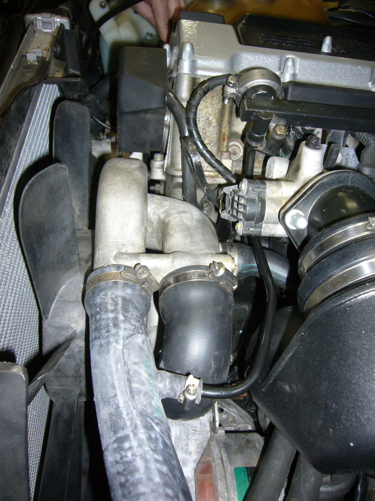
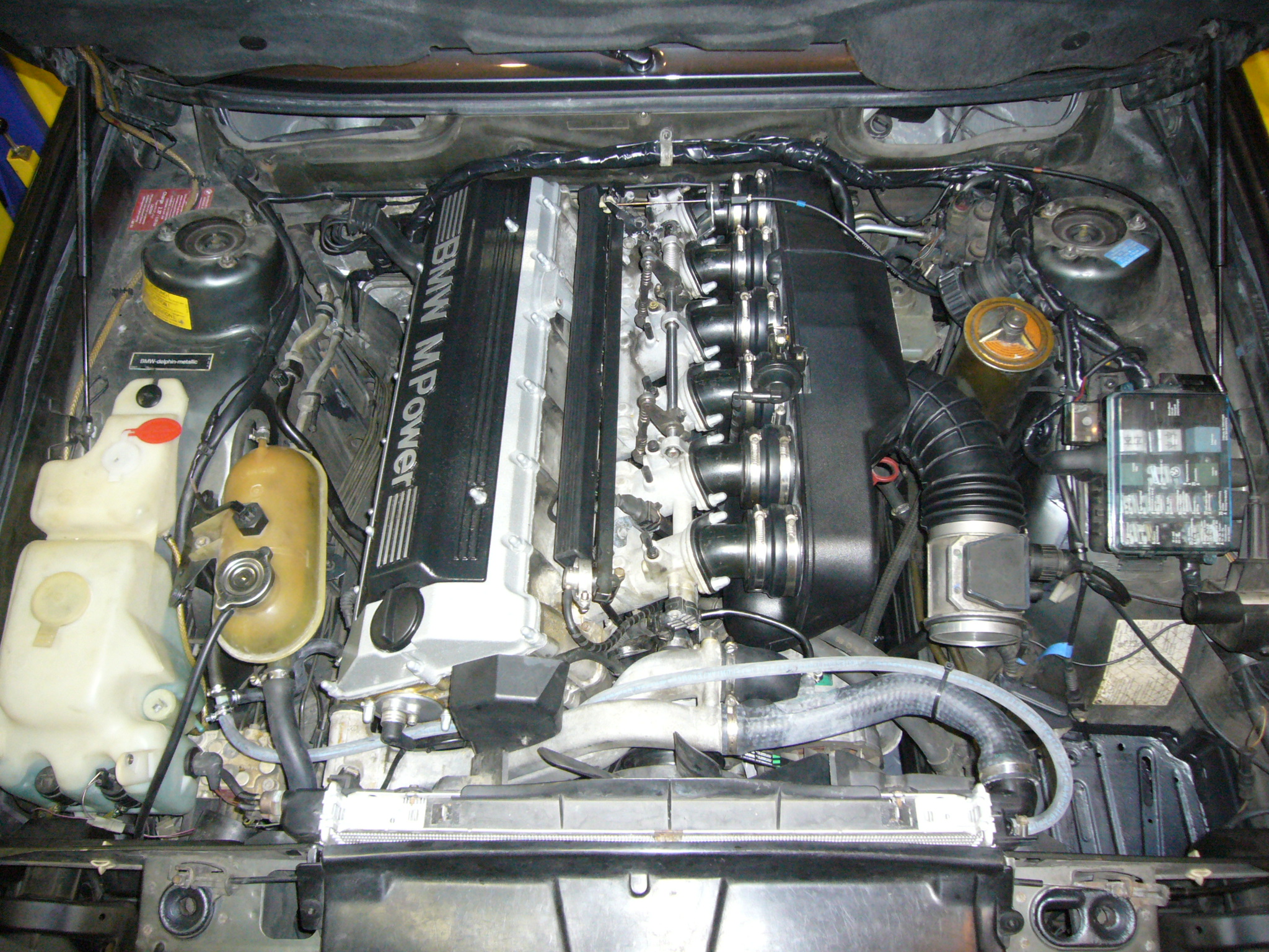
The intake plenum clears most of the engine bay, however the rubber elbow hose is a very tight fit. In fact, it is basically pressing up against the power steering reservoir and the hard line that runs from the booster, along the side of the reservoir, and down to pump. In the long-term, this hard line will need to be replaced with a custom one. But we were able to use the mounting clamp in reverse to effectively pull the hard hose down and away from the rubber intake elbow. Doing this allowed us enough clearance to be able to push the elbow onto the intake plenum.
In addition, we had to remove the bracket that used to hold the 535i's coolant expansion tank. This is necessary to do since the MAF and intake elbow sit in its location.
v. Heater valve bracket adjustment
The intake plenum will not clear the heater valve the way it is currently mounted on a 535i. There are two things that need to happen to clear this. First, the heater valve bracket has to be moved to the M5's position, and it then has to be bent backwards towards the firewall. Currently if you look at it from the side, it is shaped like a "Z", with it initially coming down, then going forward and down at an angle, and then down again. You have to bend it so that it goes backwards and down at an angle. By doing these two things, you move the heater valve over to the driver side about 1/2 to 3/4 of an inch, and further towards the firewall another 1/2 to 3/4 of an inch.
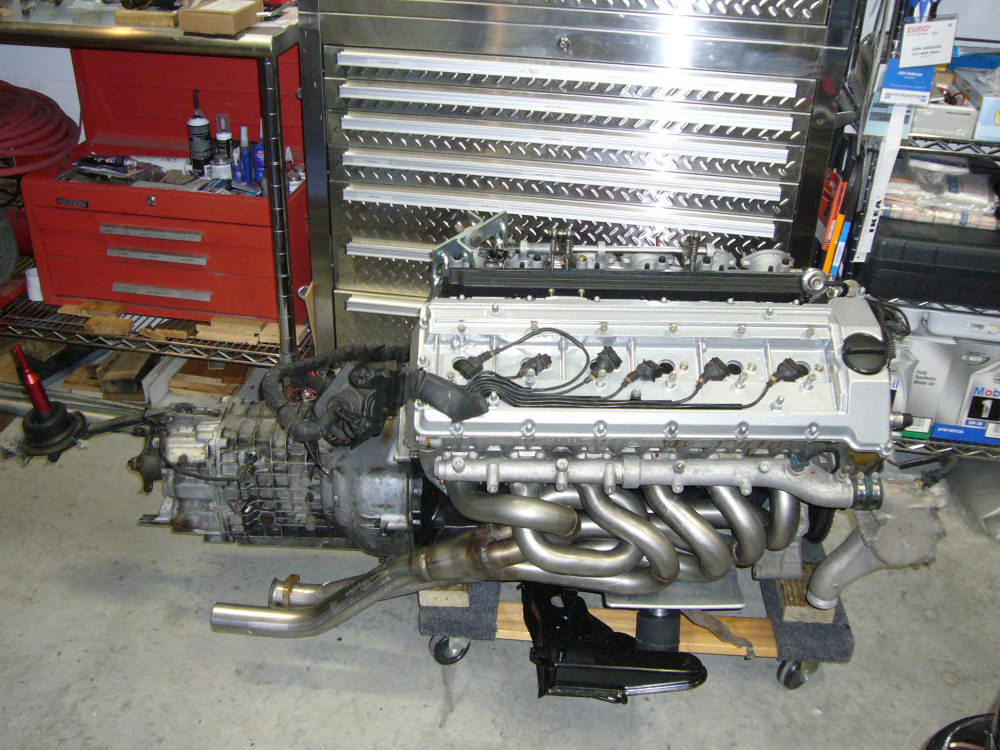
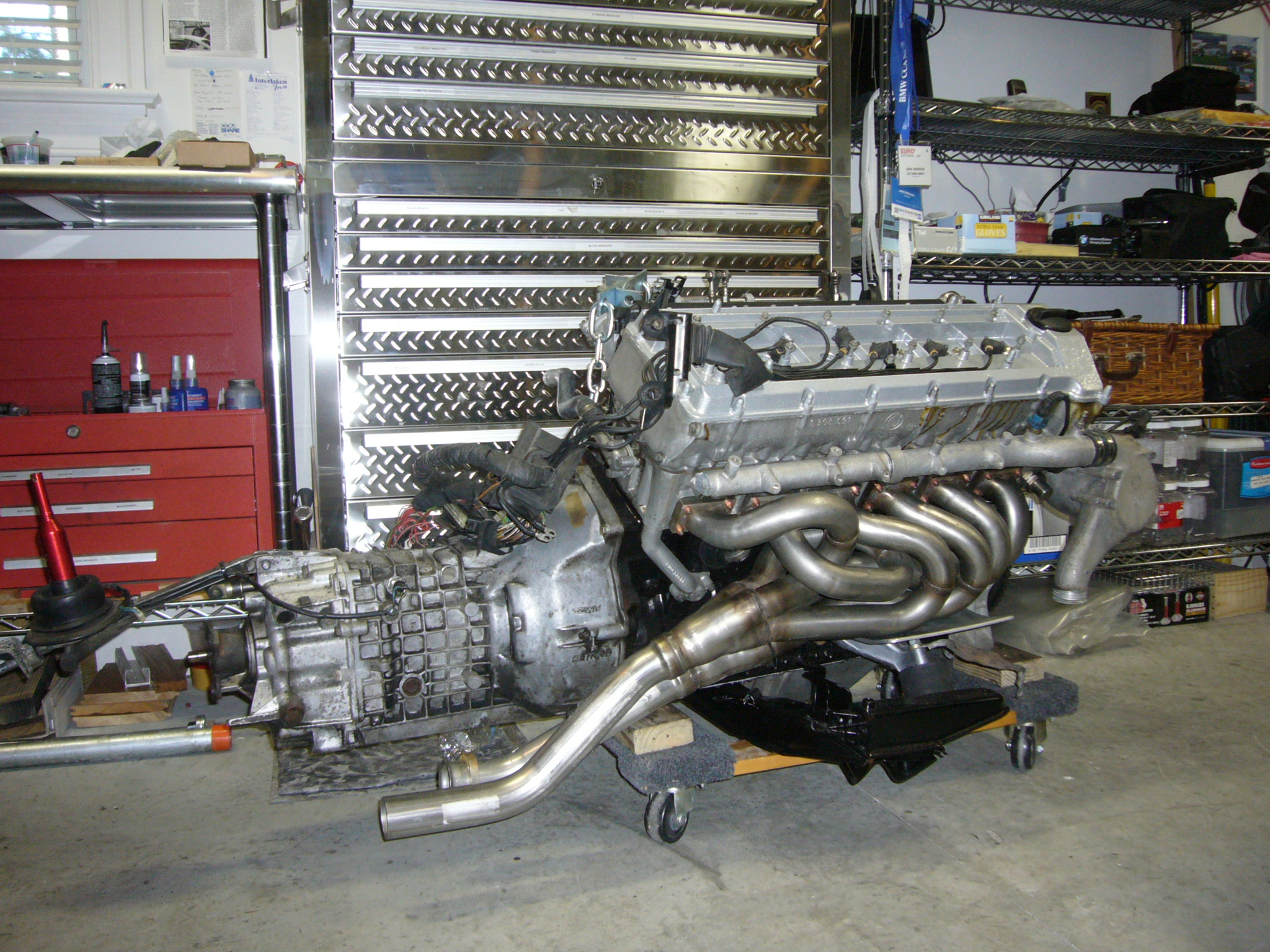
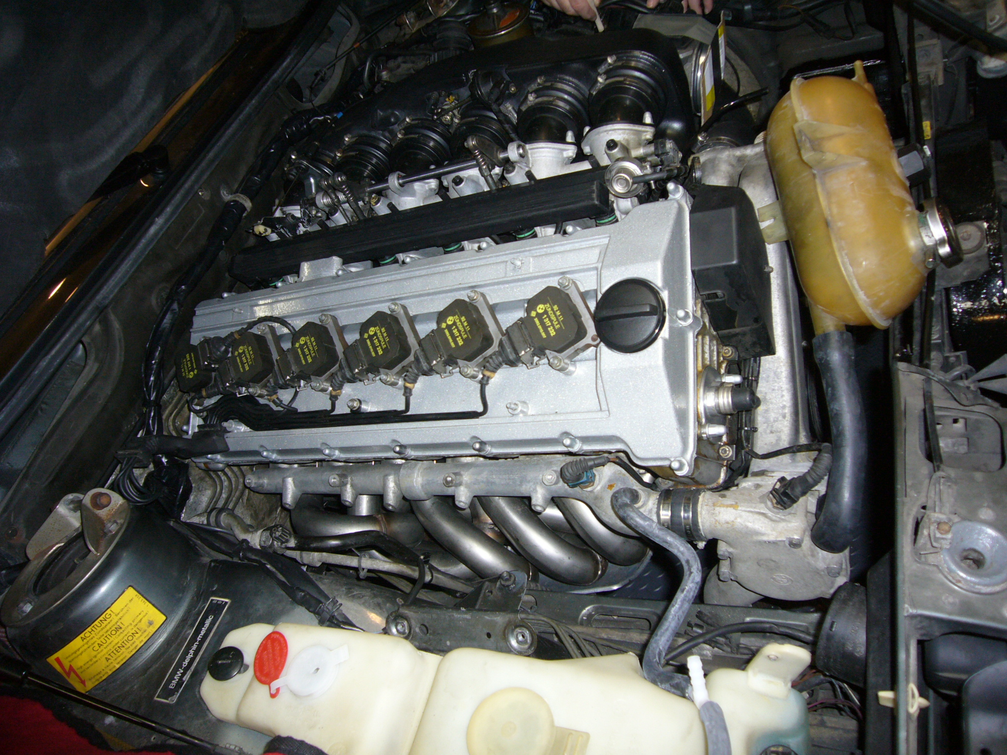
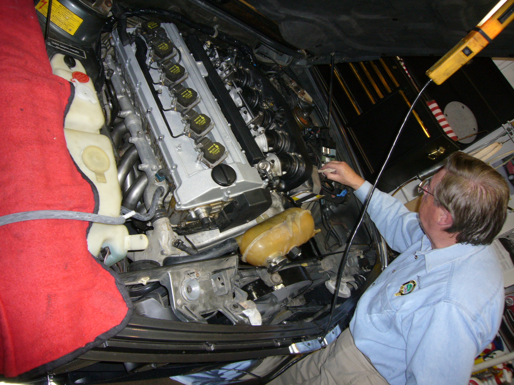
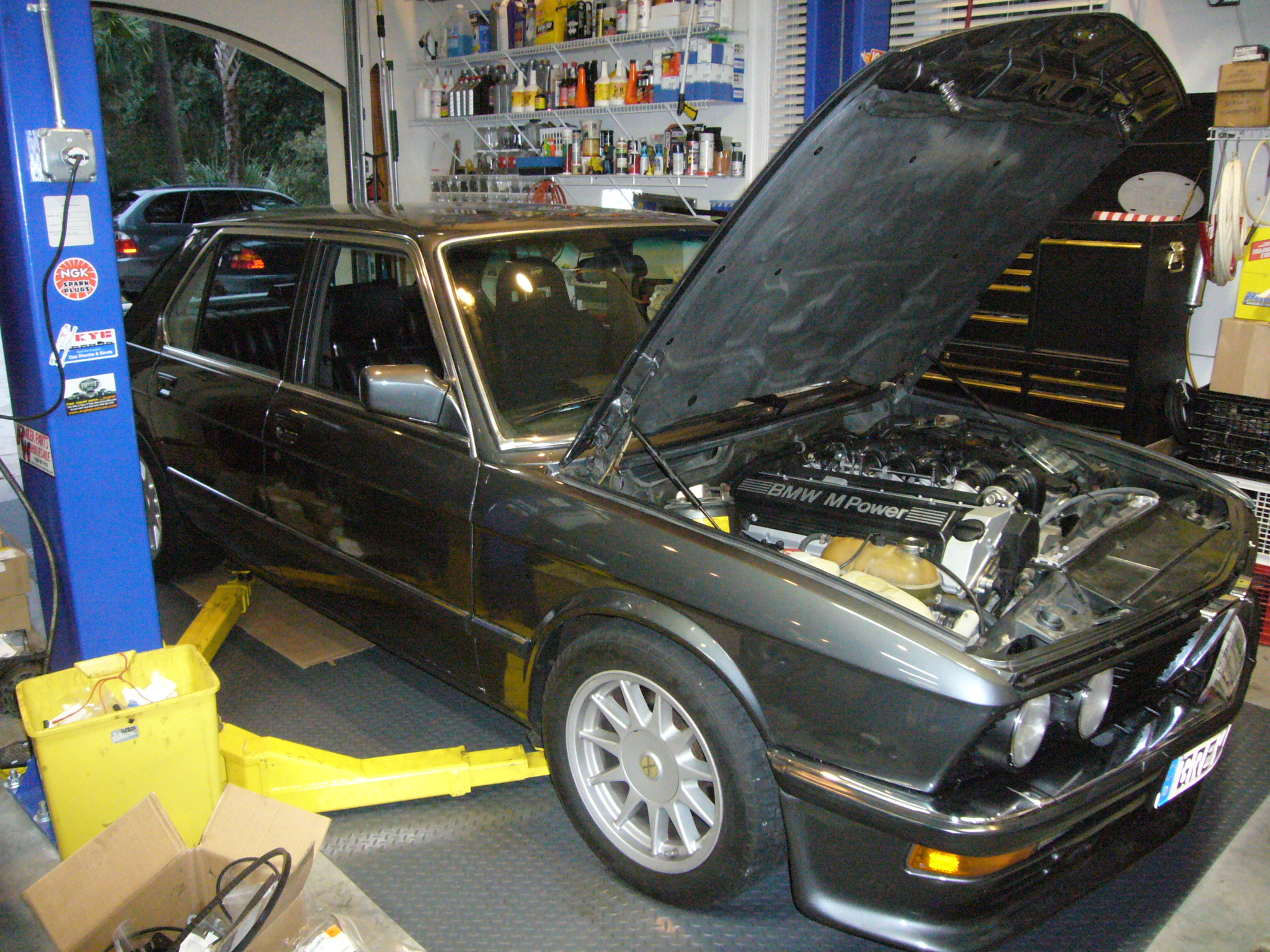
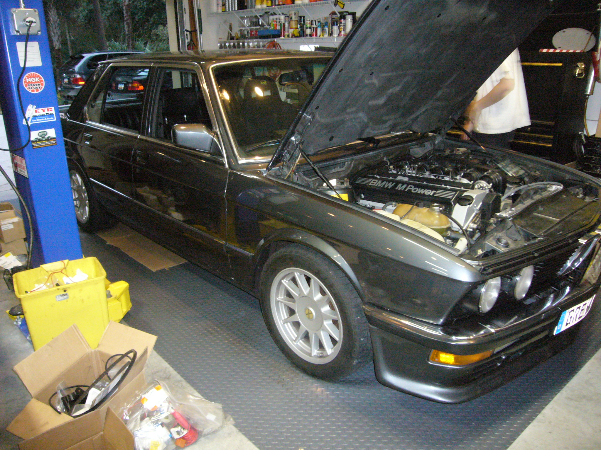
B. Engine Installation
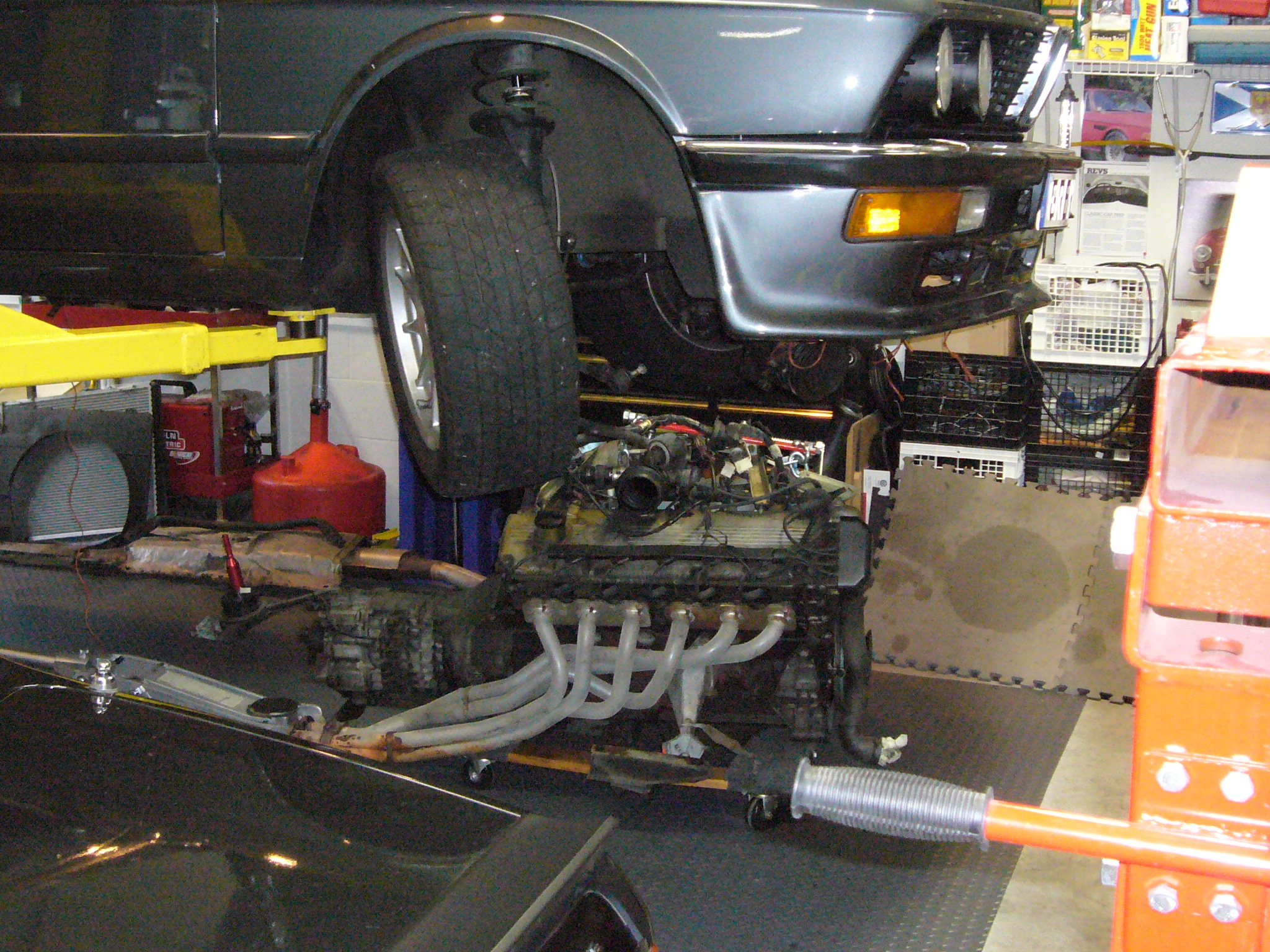
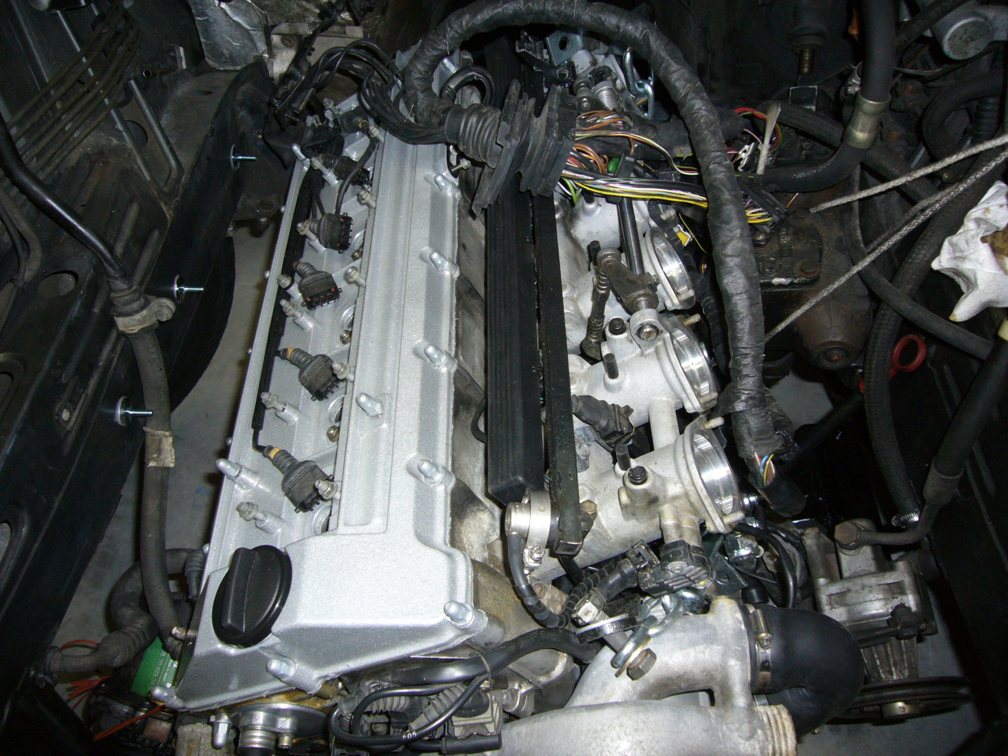
To start with we must get everything bolted together and mounted. So we started with a really nice reinforced and powder coated M5 front subframe. We decided to use an M5 subframe because it has the steering limiters for the larger wheels and tires we plan on running and also has all of the mounting points for the M5 heat sheilds. This is really critical because the M88/3 header will get really really hot. We then mounted the motor to the subframe using the solid rubber mounts from the driver's side of an M5. After this we took the lightened steel flywheel off of the M30 and mounted that to the S38. In the past I had installed an M5 clutch and pressure plate and it was still in really good condition. So this was all put in place and then the Getrag 260/6 was installed behind it. All of this was a direct bolt up and fits into the car really well. Eventually I plan on replacing this transmission with 6 speed from the Euro E34 M5. Now once the transmission was mounted I then installed the M88/3 headers. Any of you who have installed these know that it is most definitely easier to install these with the motor out of the car. Here are some pictures ready for installation.
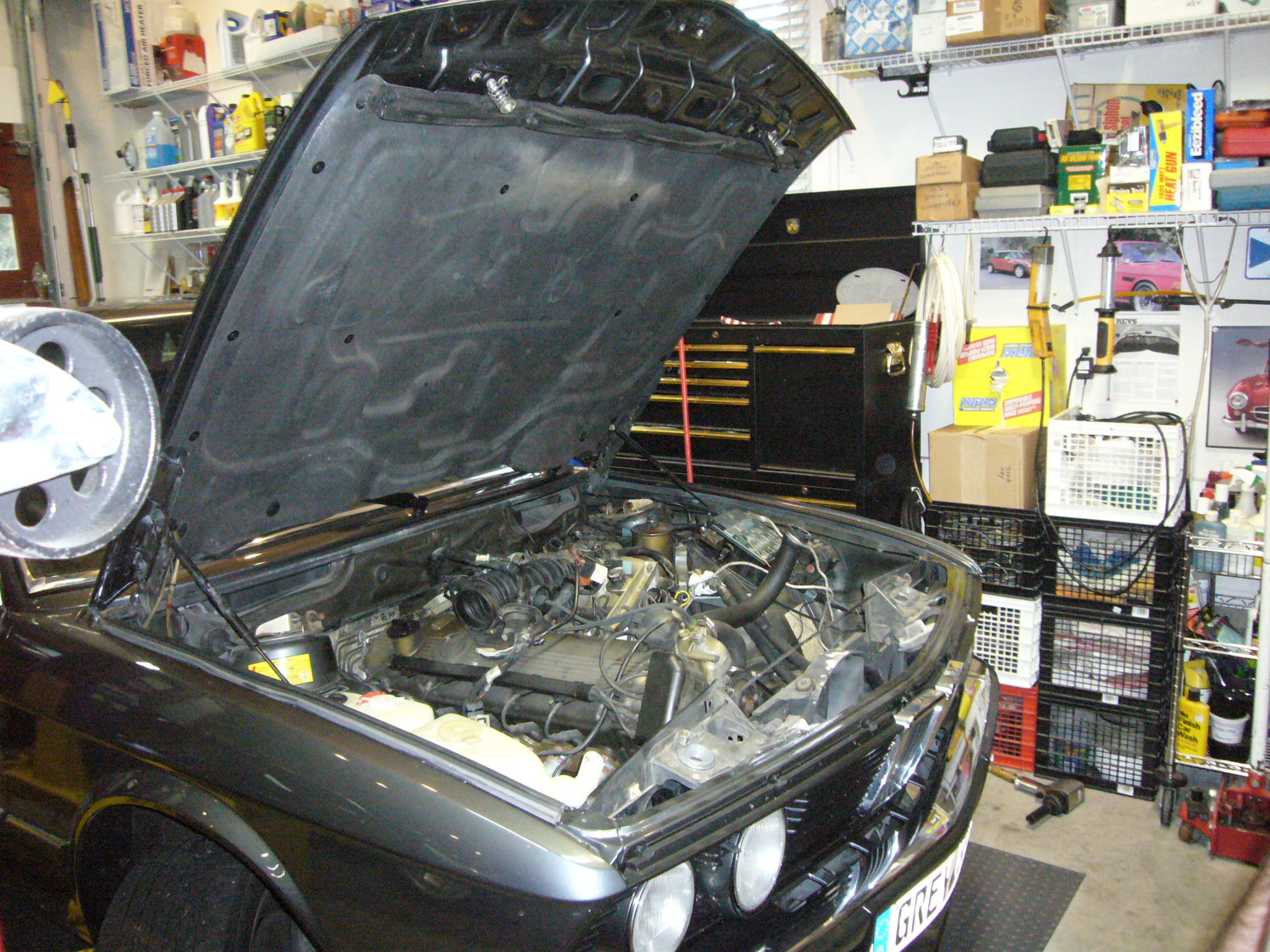
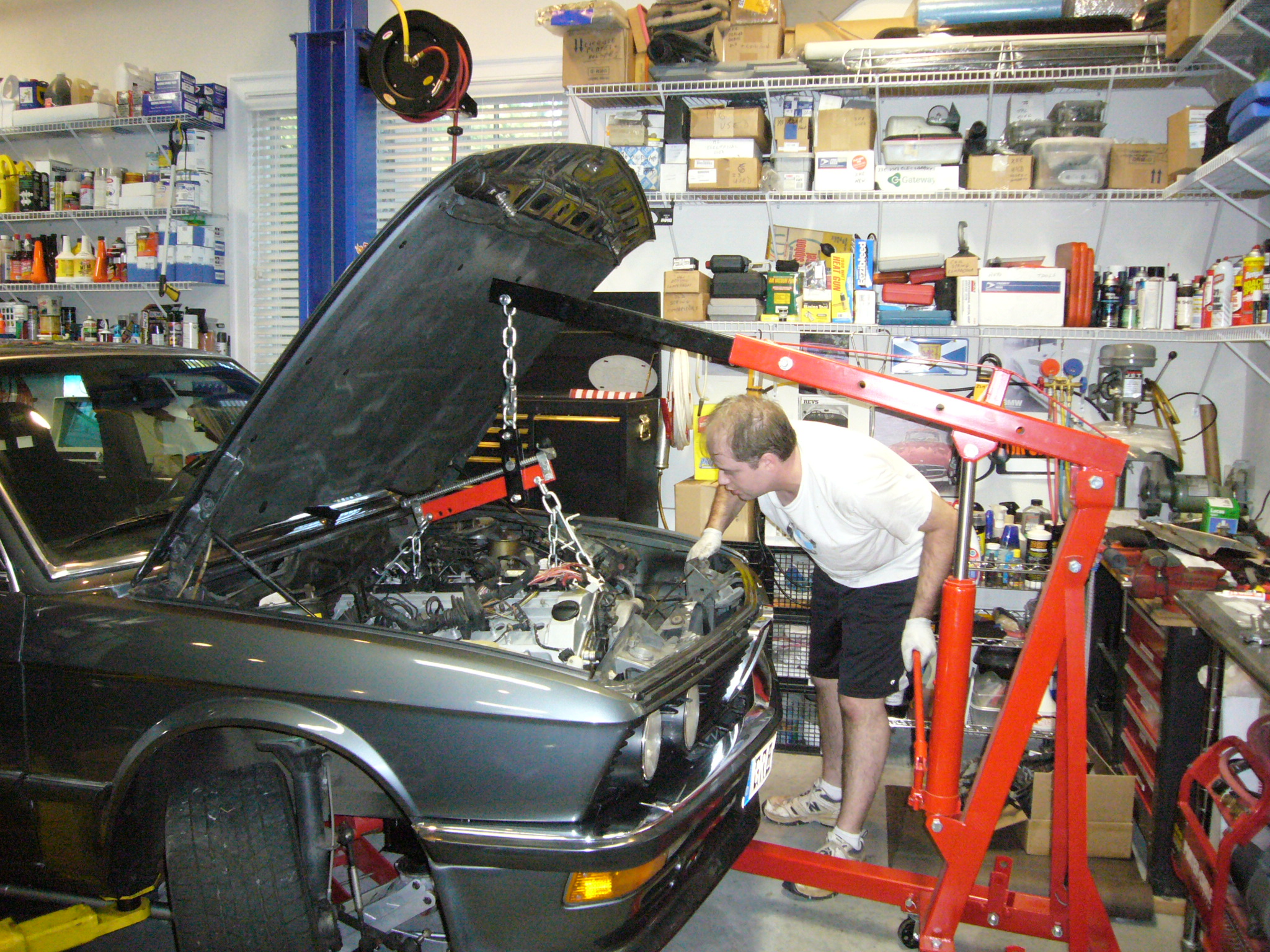
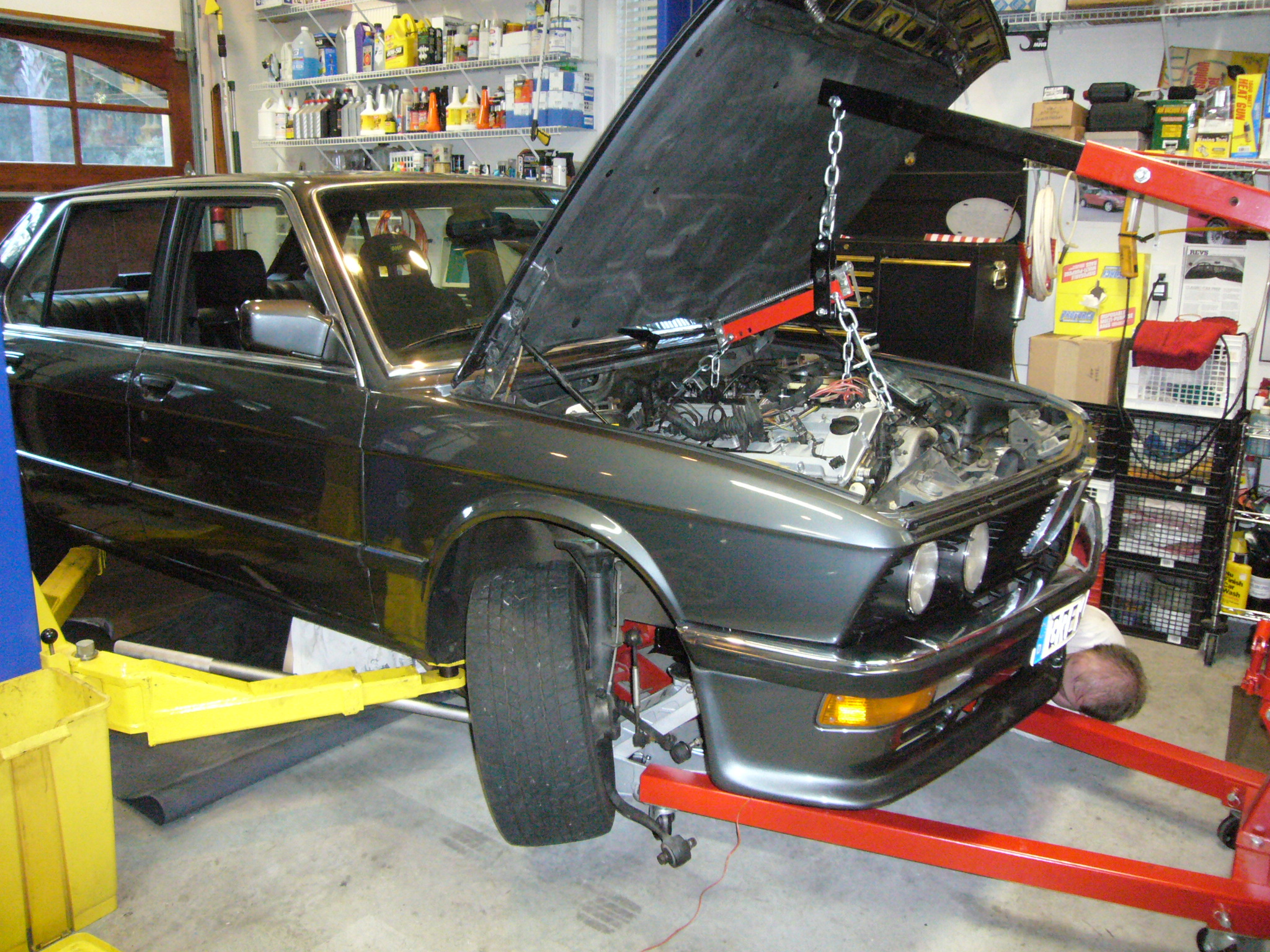
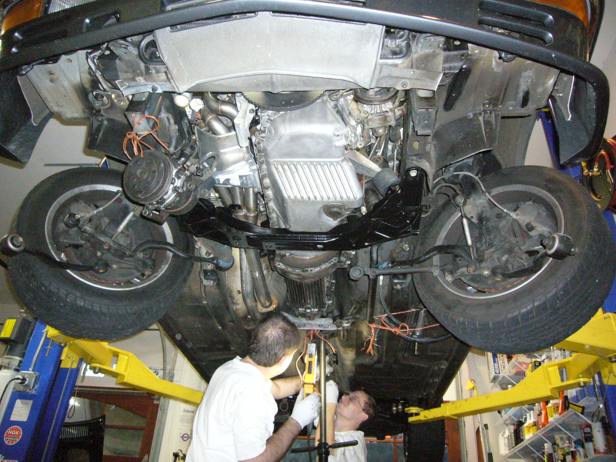
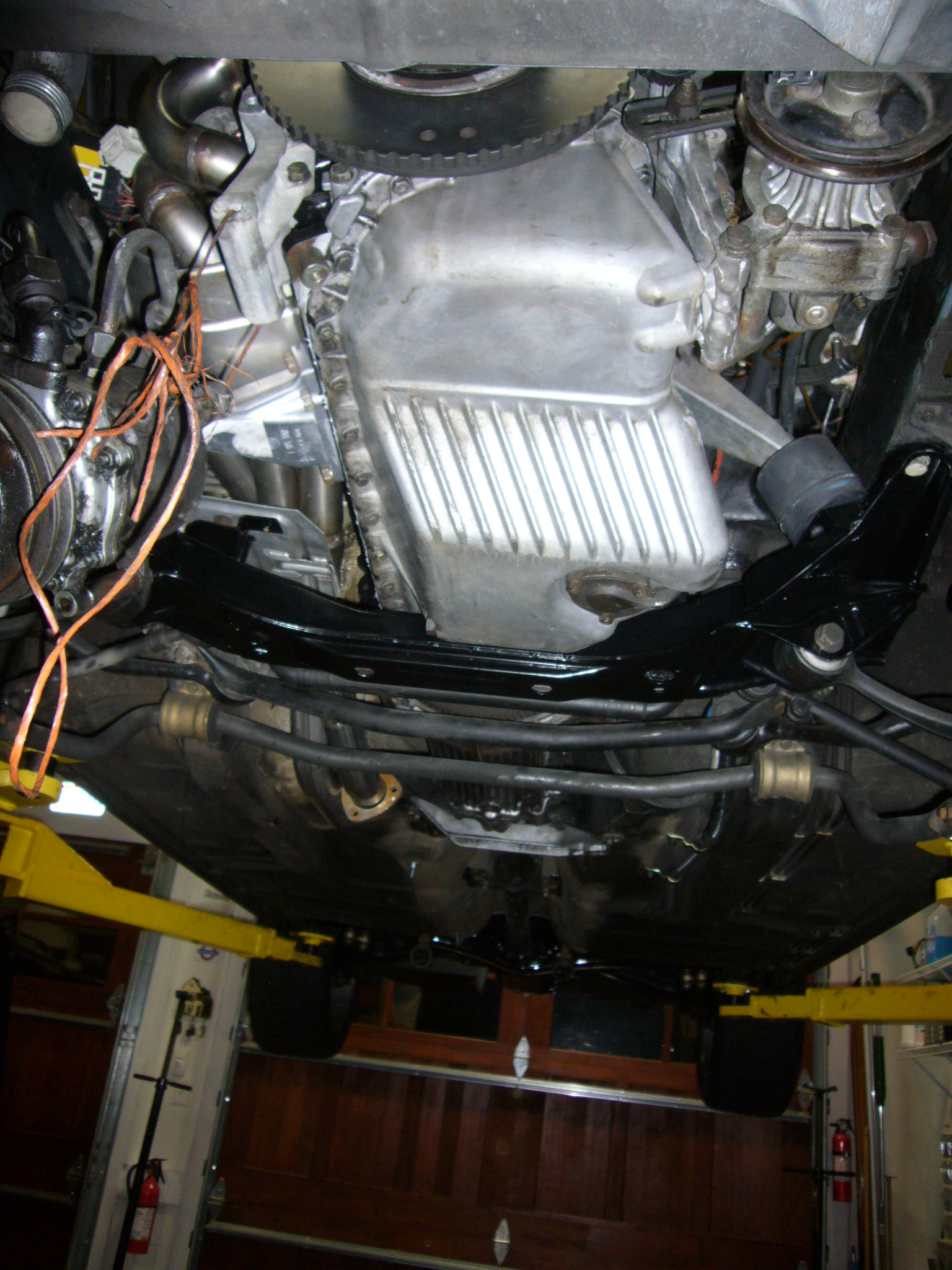
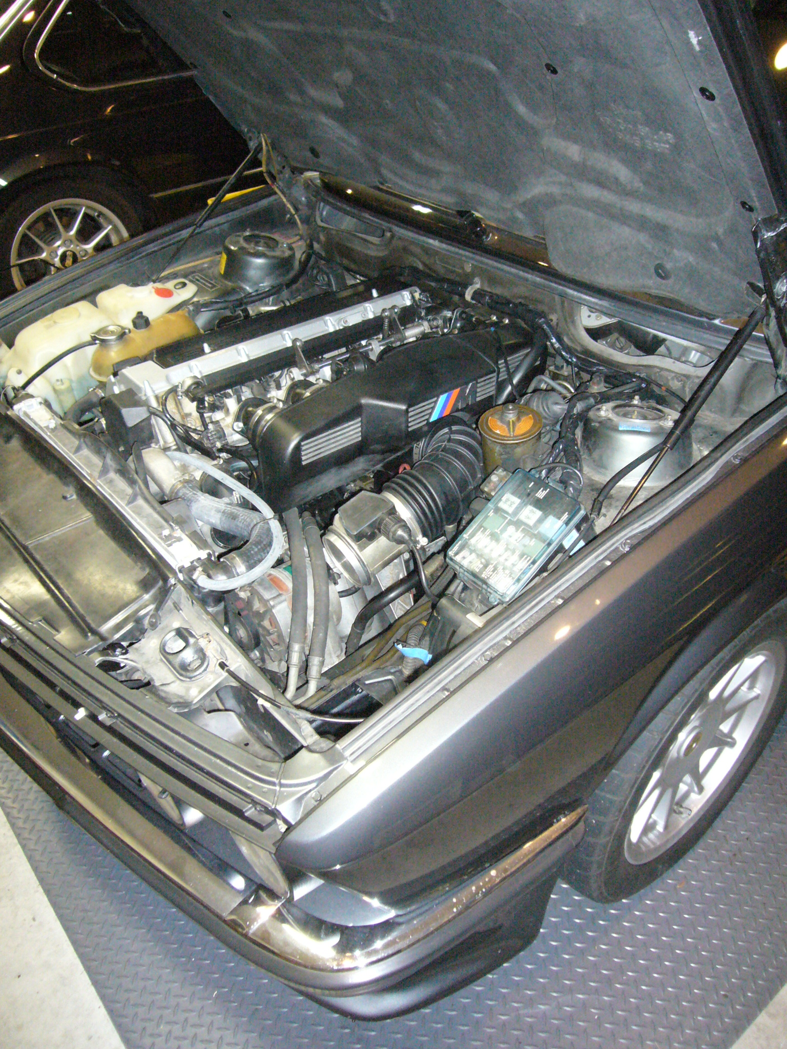
Like I said earlier I never pull a motor out the top and so as you can see here are some shots of the installation. This part is just lowering the body onto the motor.
Now after you lower the body so far you have to list the motor in using a host so that you still can get under the car to tighten the subframe bolts.
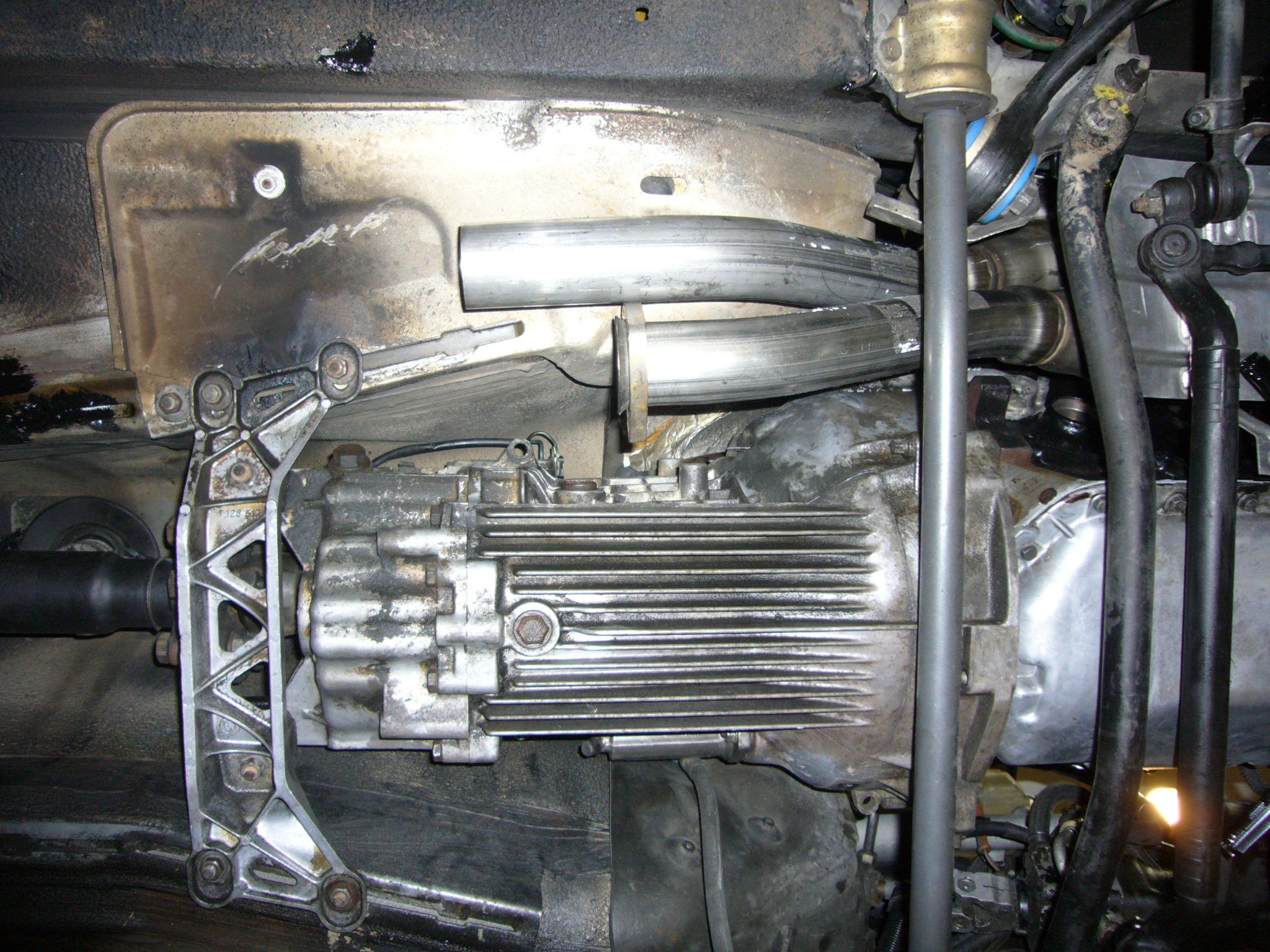
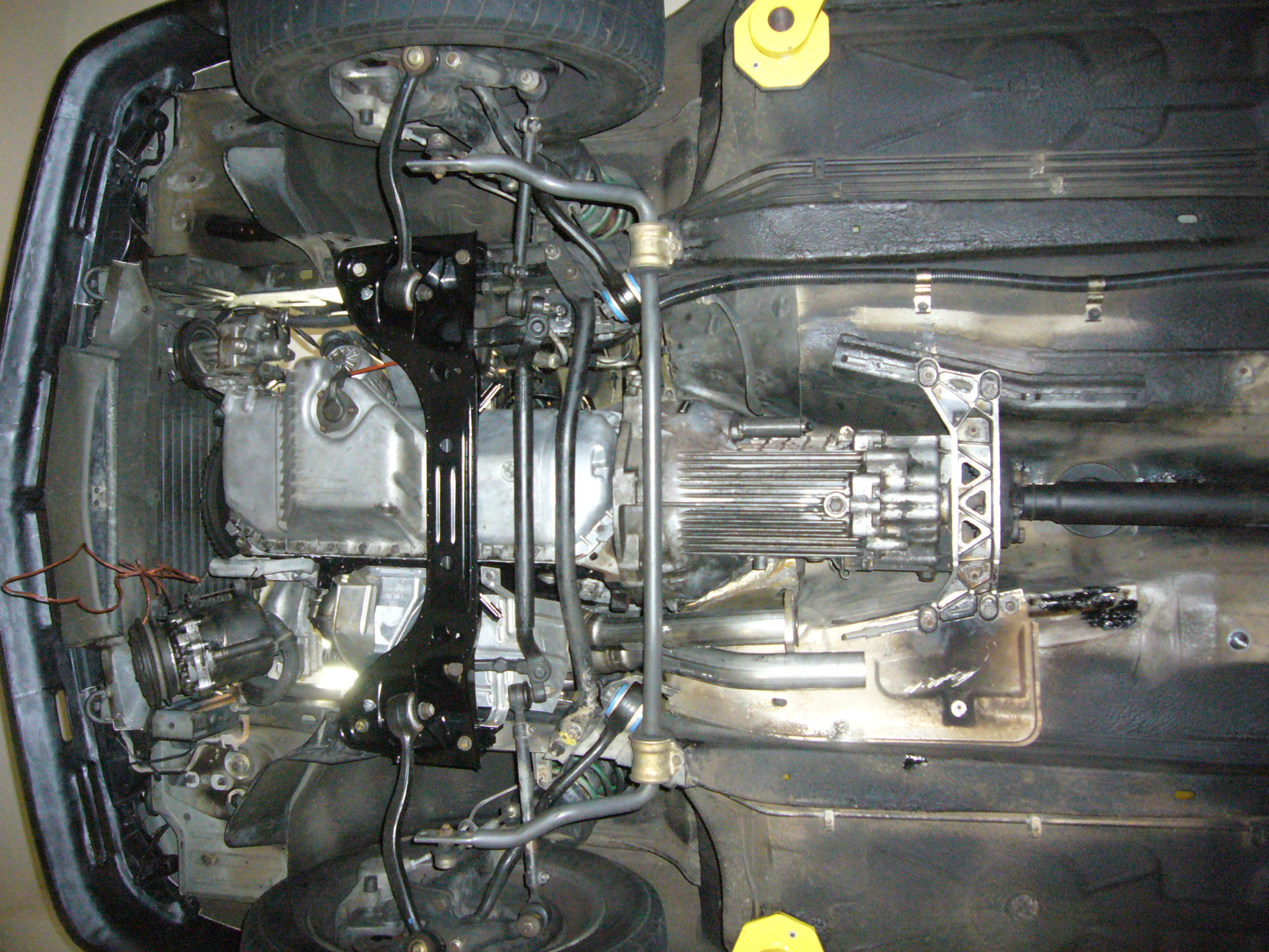
With the engine in the correct location the subframe bolts and transmission cross member are tightened into place. This then allows use to reconnect everything under the car, suspension, driveshaft, etc.
She is really starting to look good from the underside. So now we can move on to some other connections.
C. Other Considerations
i. Expansion tank and other coolant system changes needed to interface to E28 chassis
It is somewhat suprising how we were able to use almost all unmodified BMW hoses.
We were able to use the following B38 hoses:
-- The upper radiator hose, which includes the breather from the head.
-- The water pump supply hose.
-- The "bushing" between the coolant cross tube assembly and the side of the head tube.
-- The heater core return hose.
-- The expansion tank supply hose to the coolant tubes.
-- The side of the head tube breather hose.
The follow E28 M5 hoses we able to be used:
-- The heater core supply hose.
-- The heater core valve supply hose.
The only modified hose is an E28 M5 lower radiator hose which was able to be cut down to be used as the lower radiator hose.
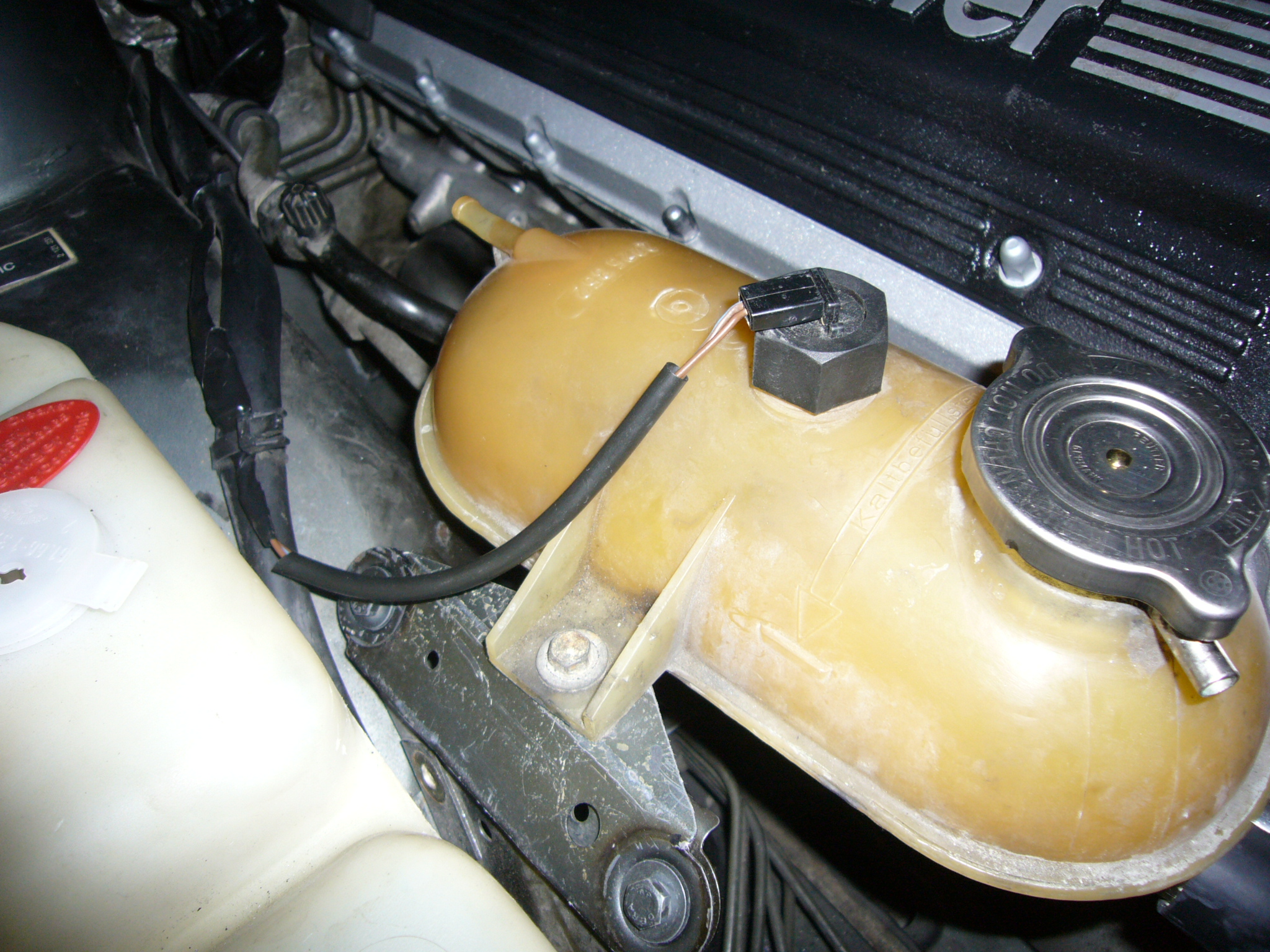
Now we moved on to the overflow/breather hoses. The B38 is slightly different from the B35 when it comes to these breathers. The E34 has the coolant expansion tank on the right side of the motor. The E28 has it on the left. The differences are as follows. The E34 uses a plastic tube to get the radiator breather from the left to the right side of the car. The head breather on the E34 is actually linked directly into the upper radiator hose, not the coolant expansion tank like on the E28. The E34 has something the E28 doesn't have. The E34 has a breather on the tube that runs down the side of the head. Now we decided that we were going to move the radiator overflow from the left side to the right side. This was accomplished by using a metric to standard pipe thread adapter in the right side of the radiator in the highest opening. Then a pipe thread to hose bib was used to allow for the breather hose to be attached.
All we can say about this set-up is that we have witnessed about the same amount of overflowing coolant back to the tank in my car as the M635, which is factory plumbed. At the current time I don't see any problems because the car runs really cold and honestly I haven't put enough miles on it to be able to say 100% that it won't eat radiators. But there are others with 3.6L who have done it like this with no problem.
I think the key is though that the B36 and B38 have the vent on their coolant tubes on the side of the head and we have plumbed directly back to the tank. That allows for the boiling coolant to come out when it gets out of the head. The travel of the coolant across the motor to the top of the rad does not lead to more heat being placed in the coolant. And the little boiling coolant that comes from the head breather doesn't have enough effect to change the temp in the upper hose. So my feeling is that we would have no boiling water coming into the rad especially since the motor is running on the cooler side of things and then I am just using the breather on the rad as thermal expansion so the rad is not super stressed between full running temp and turning the motor off.
Now lastly some people question why I decided to use the B38 cooling plumbing when I could have just taken B35 plumbing and installed that without any questions or issues. This is very simply answered. The B38 has had issues with overheating the Numbers 1 and 6 cylinders. This issue is something that I have been very concerned with. I decided at that time that it was super critical for me to use the best cooling system I could. The B38 cooling system can flow more and therefore exchange more heat than the B35 system. Now this leads to some other things that were done to help keep the car as cool as possible. First off we switched the aux. cooling fan switches to the unit out of an E36 318i. This unit has an 80 degree C low temp switch and an 88 degree C high temp. This means I get the low speed of the aux fan to come on when the gauge in the dash is at 12 o'clock. I did want to run a lower temp thermostat but unfortunately there is not one made. Some have asked why I didn't use a larger radiator or a custom one. My statement was simply that I had this one and to be completely honest our calculations showed that with fan help this will work. With that being said the only part left that is somewhat different is the coolant temp sending unit for the dash. I wanted to have the wiring harness plug and play so I got a sensor from a later E24 635 which an M30 B35. This sensor has the correct plug and the correct calibration for the gauge.
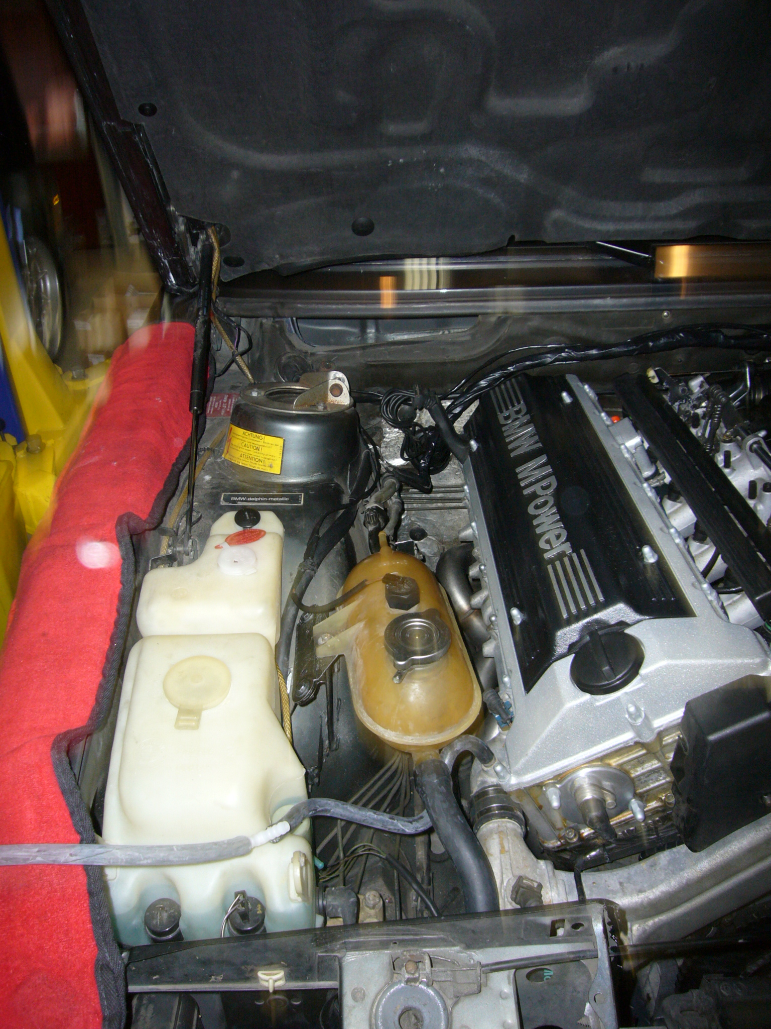
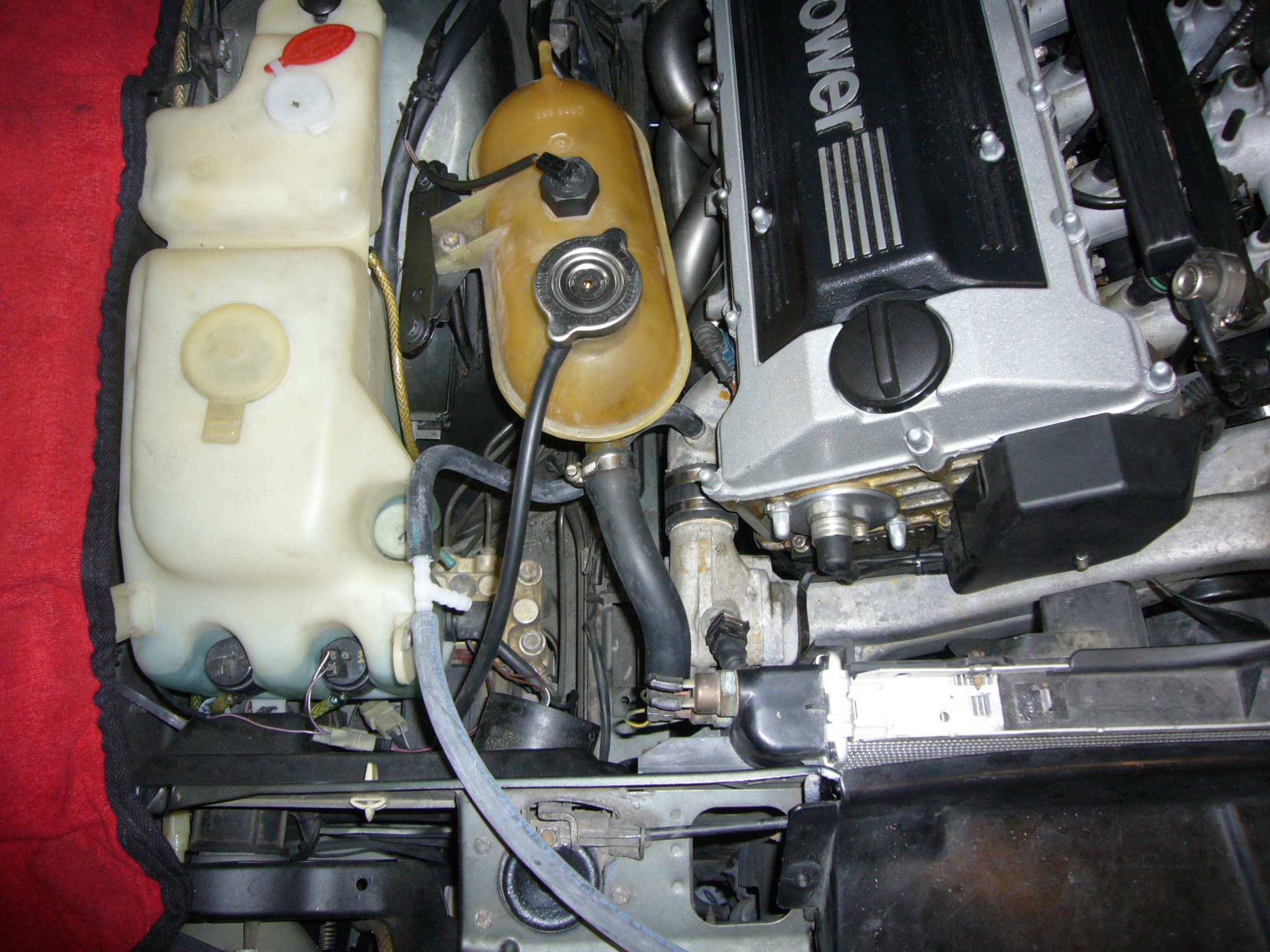
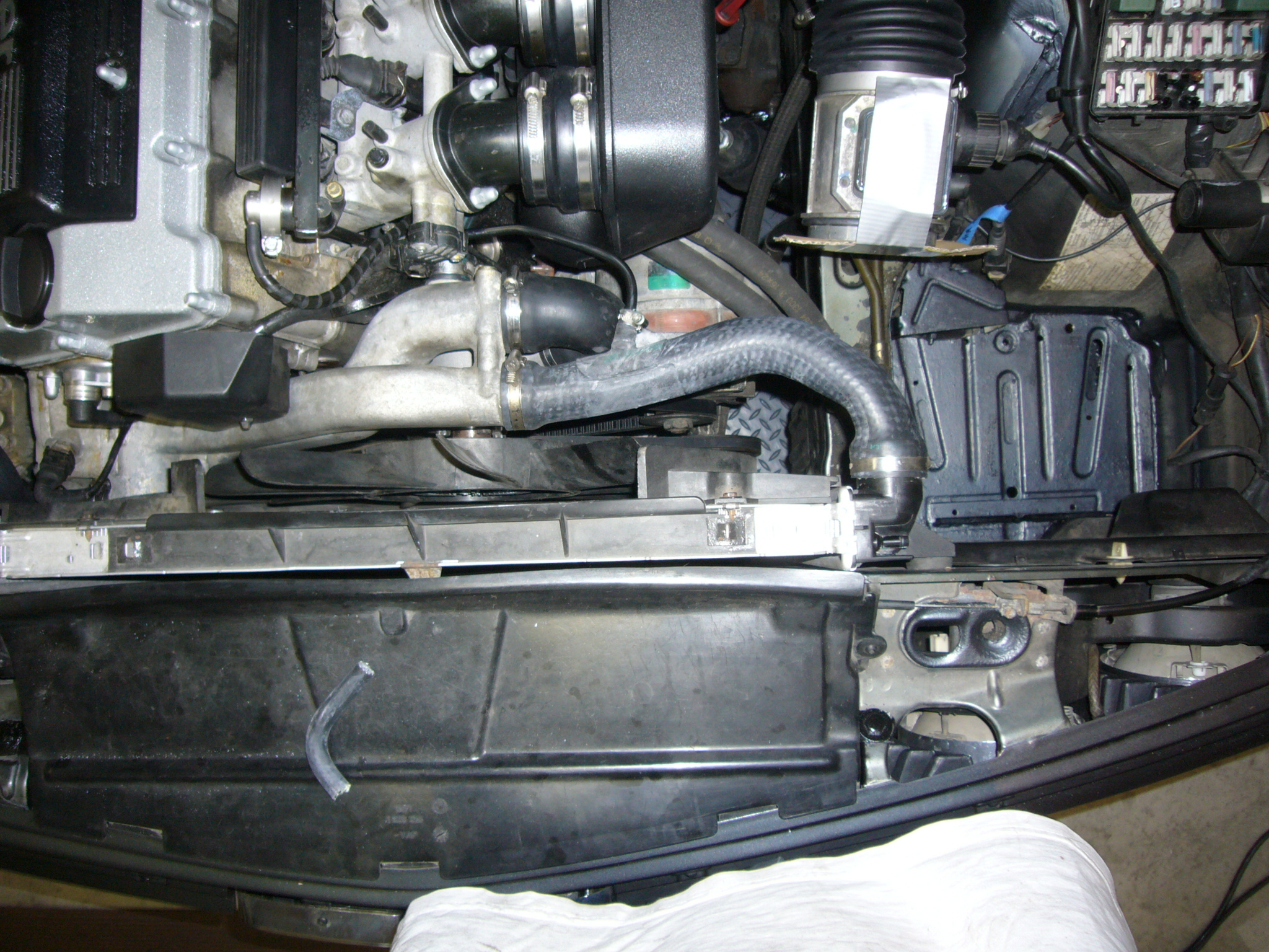
In addition to these modifications, we had a spare (from a wreched car) E28 535i intake filter box mount, which we were able to modify to use as a mount for the E28 M5 coolant expansion tank. This was completely custom, and we don't have exact pictures as it was made to fit. However from the pictures you can tell we were able to use the stock S38 B38 coolant tube.
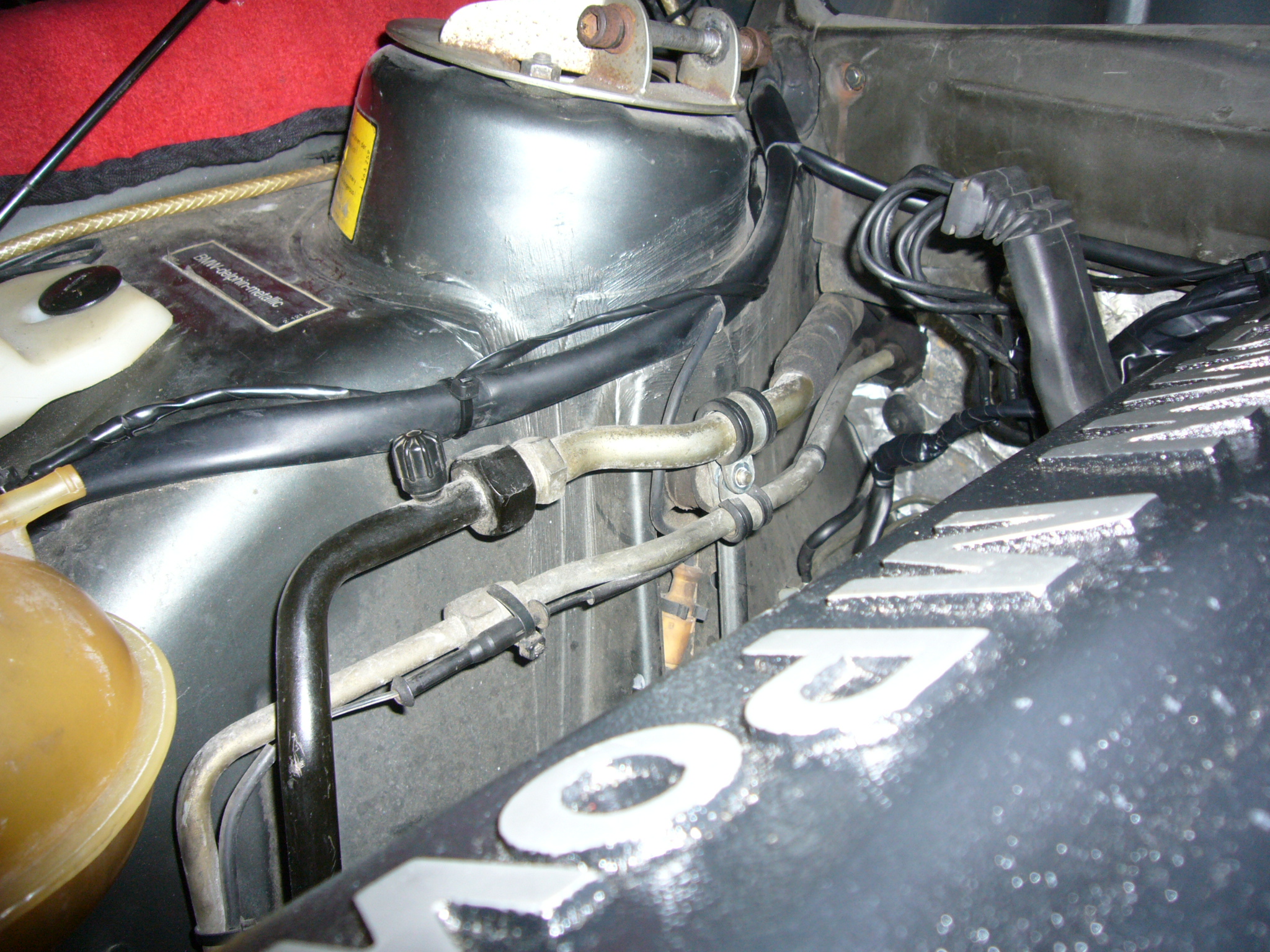
ii. PS hoses and clearance to reservoir tank, adjustment
One of the trickier bits of the installation, as we were not certain that the motor could fit with the current power steering hoses and reservoir tank in the E28. All of our research indicated this would be a tight fit, and it was!
The key issue is that the intake boot is right up against the side of not only the PS reservoir, but that the hard line that runs next to the reservoir interferes with the intake. What we had to do, was switch the bracket that holds the line to the side of the reservoir, so the line sat behind the bracket, and we were able to fit the intake boot on. This is ok, since the only major problem will be the rubbing of the intake boot, and it is very tough rubber. What we should do in the long term is make a new hard line that runs behind the PS reservoir to avoid the interference.
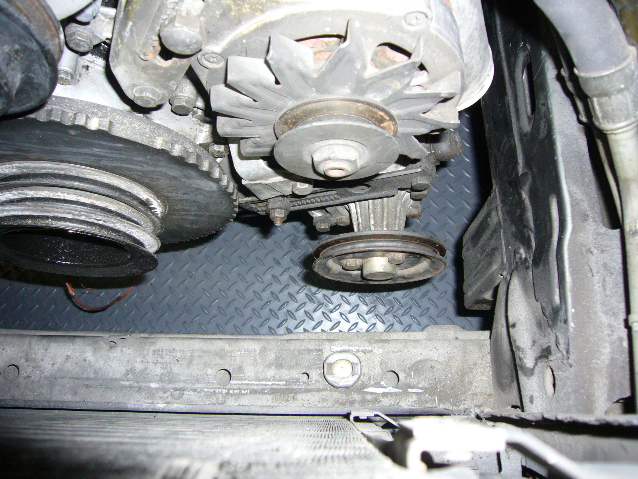
Also, to clear the alternator, we had to relign the banjo fitting of the rubber line going to the top of the PS pump. This was easily accomplished, although you must replace the crush washers. Also a special belt length is required because of the different size of the crank pulley.
iii. Removal of airpump and AC system
The S38 B38 comes with an auxiliary air pump driven off the serpentine belts. This was used to meet cold-start tailpipe emissions requirements in Europe. Since the car is registered in a state that doesn't require emission testing and the vehicle is almost 25 year old, we removed the air pump. This made fitting the M88 exhaust a non-issue.
In addition we decided that the removal of the B38 accessory bracket would be a good idea since it is significantly larger and heavier than the E28 accessory bracket. With some quick research we were able to determine that the E28 bracket bolted up to the motor and that the mounting points for the compressor were the same distance from the front of the crank. We then moved on to the compressor. With a little cross referencing we were able to determine that the B38 compressor is the same as the late E24 M6 compressor. This meant that it bolted to the bracket without a problem and lined up perfectly with the crank pulley. Please note that a special length belt is needed because of the usage of the E28 bracket.
Now onto AC lines. Some people ask why we didn't just use the E28 M5 lines. There are 2 answer to this question. The first is that the B38 compressor will not bolt up the the E28 lines. The B38 compressor is much longer and also does not have the angle on the low pressure side fitting. The second answer is that the B38 thermostat housing does leave room for clearance for the E28 M5 AC lines. That being said we decided not to use the E28 compressor and M5 lines since we knew we would need to have custom lines anyway. In addition we also really liked the idea of using the B38 compressor as it was designed to be used with R134A and also is significantly larger therefore allowing for much better cabin cooling which is a must.
To test the system and make sure there are no leaks I wired the compressor into the original E28 AC wiring as if it were an E28 compressor. In a later section we will talk about the changes to the wiring for the AC system
iv. 140 amp alternator
We were able to use the 140 amp alternator that came with the S38 B38, with minor wiring modifications, as noted in the narrative above. One note is that a special belt length is required because of the usage of the E28 accessory bracket.
v. Oil cooler lines
We wanted to keep the stock E28 M5 oil cooler lines already fitted to the car, as noted in the narrative above, by retrofitting the E28 M5 oil filter cannister to the S38 B38.
D. Wiring considerations
i. Removal of air pump
We removed the air pump, and all the wiring and plugs associated with the running of the air pump was left unplugged.
ii. Wiring loom – removal of superfluous wiring
The wiring harness was modified in 3 ways.
First we had to cut off the X20 plug, and then wire the right engine wiring harness side plugs to the C101 connector on the side of the E28 fuse box. The E34 loom isn't long enough to reach across the back side of the engine and then down the inner fender, so we cut off a spare C101 connector with approximately 24" of wires to be able to lengthen the wiring harness to reach the fuse box. The pin outs are located in the next section.
Second, we pulled out the wires having to do with the A/C control, and routed them from the ECU to down the passenger side inner fender. These are explained in the following section.
Third, we pulled out 4 wires having that used to go to the X20 plug on the E34, and routed them through the hole in the firewall to the C103 connector in the cabin near the ECU above the glove box. The pin outs are described in the section below.
We did not change the way in which the cruise control worked. It still works like the E28 way. Although we had to use an E24 M6 cruise cable to have the extra length needed to reach the throttle lever on the intake. Also, the main ground strap was moved as per the battery discussion.
A few installation notes on the S38 B38 wiring harness: (A) there is a 3-pin plug that goes into the E34 E-box for the coolant fan wiring; (B) ther eis a 2-pin plug that goes to the E34 E-box fan temp sensor. Both A and B were not used. (C) We removed the 15-pin plug and associated wiring that led to the top-speed limiter control unit. (D) The O2 sensor is trigged off the air pump relay, and thus does not need to be connected to pin 6 on the C101 connector. (E) there is a 1-pin plug that is the starter trigger signal to the DME.
iii. X20 to C101 plug connections
Connection (E28) Color (E28) C101 (on body) X20 (on motor) Connection (S38 B38) Color (S38 B38) Alternator Output Blue 1 25 Alternator Output Blue Static Oil Level Blue/Violet or Blue/Rd 2 1 Static Oil Level Blue/Yellow Coolant Temp sensor Brown/White 4 12 Signal for Coolant Temp sensor Brown/Violet O2 Relay Power Green/Yellow 6 not used Fuel Pump Power Green/Violet 7 13 Fuel Pump Power Green/Violet Starter Trigger Black/Yellow 8 18 Starter Black/Yellow To Diagnostic Plug White/Black 10 pin 16 on diag. plug Diagnostic pin for power in run/start Green/White Power coil from fuse 1 Green 12 21 Switched Power from Key Switch Green Dynamic Oil Level Blue/White 13 2 Dynamic oil level Blue/White Oil Pressure Light Brown/Green 14 23 Oil Pressure Light Brown/Green Service Indicator White/Blue 14 19 Goes to data link connector pin 7 White/Green
iv. Diagnostic plug wiring (same except needs power)
In order to be able to check codes and communicate with the DME, we wanted to keep as much of the diagnostic plug of the S38 B38 engine wiring harness intact as possible. What we did not do, is wire in a check engine light into the dashboard, although this would be entirely possible to do with the right wire output, and the DME has this capability.
In order to be able to reset the SI lights, we had to connect the C101 plugs through the X20 plug to pins 7 and 16 on the diagnostic plug. In reality, you only need pin 7, but pin 16 is needed to use the Peake reset tool.
v. AC wiring
As far as AC is concerned, currently I have the AC on Signal spliced into the AC wiring of the car. The AC on signal from the switch is spliced to the DME via pin 6 on X20. In the future I will have to add a relay for the compressor control. Basically the AC compressor on is going to run into pin 30 of the relay. It will also run into pin 86 and be spliced into the DME. Then pin 85 will be grounded into the DME as the full throttle switch off. And then pin 87 will run out to the clutch. These will use pins 4,5,6 on X20 to control the A/C, where pin 4 is the AC compressor on signal, pin 5 is from the A/C pressure switch, and pin 6 is the AC on signal.
vi. C103 connector
In addition to connecting the S38 B38 engine harness into the C101 plug on the side of the E28 fuse box, we had to wire up the connections to the C103 plug under the dash behind the glovebox. Also, it's important to note that you do not wire up the DWA signal for the OBC (unlike in an E28, where you need the signal to start the DME, the B38 does not need this), and also that you need the vehicle speed input to the DME, which we spliced in from a wire from the speedo (to the OBC), and ran it across behind the dash to the glovebox side, to pin 4 (which was unused) on the C103 connector.
Connection (on E28) Color (on E28) C103 on body X20 on engine harness Connection (on S38 B38) Color (on S38 B38) RPM input black/blue 1 20 RPM output Black Code to allow Main relay start Green 2 NOT CONNECTED Anti-theft control, pin 7 NOT CONNECTED Present fuel rate White 3 24 Fuel Economy Guge White/black Vehicle speed from OBC N/A 14 Vehicle Speed Black/white
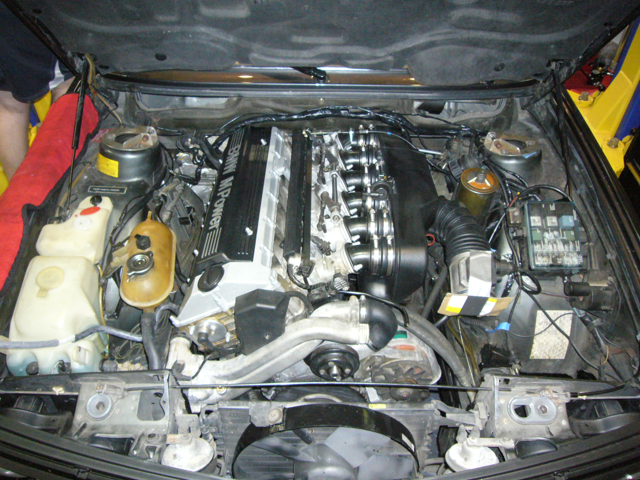
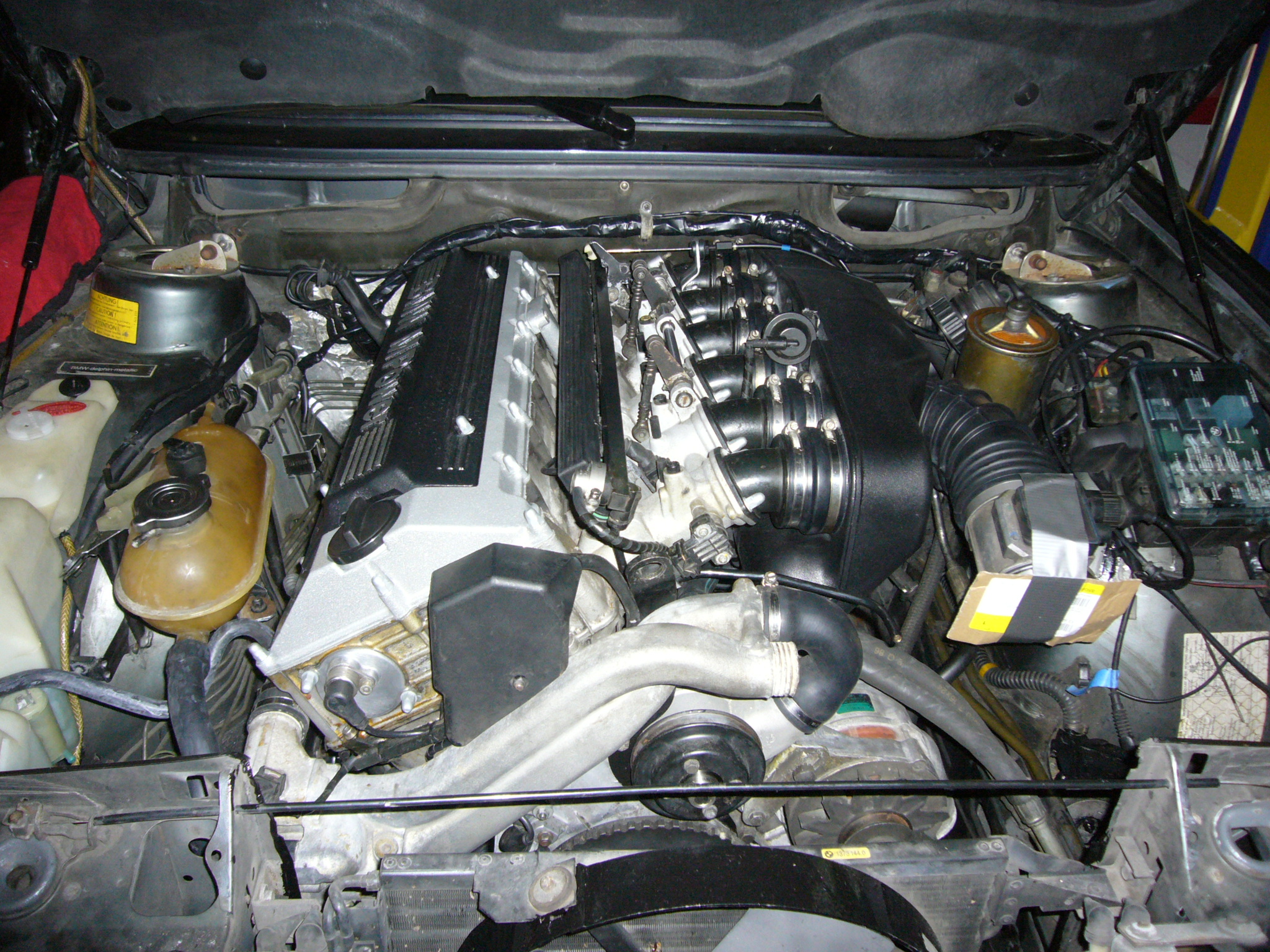
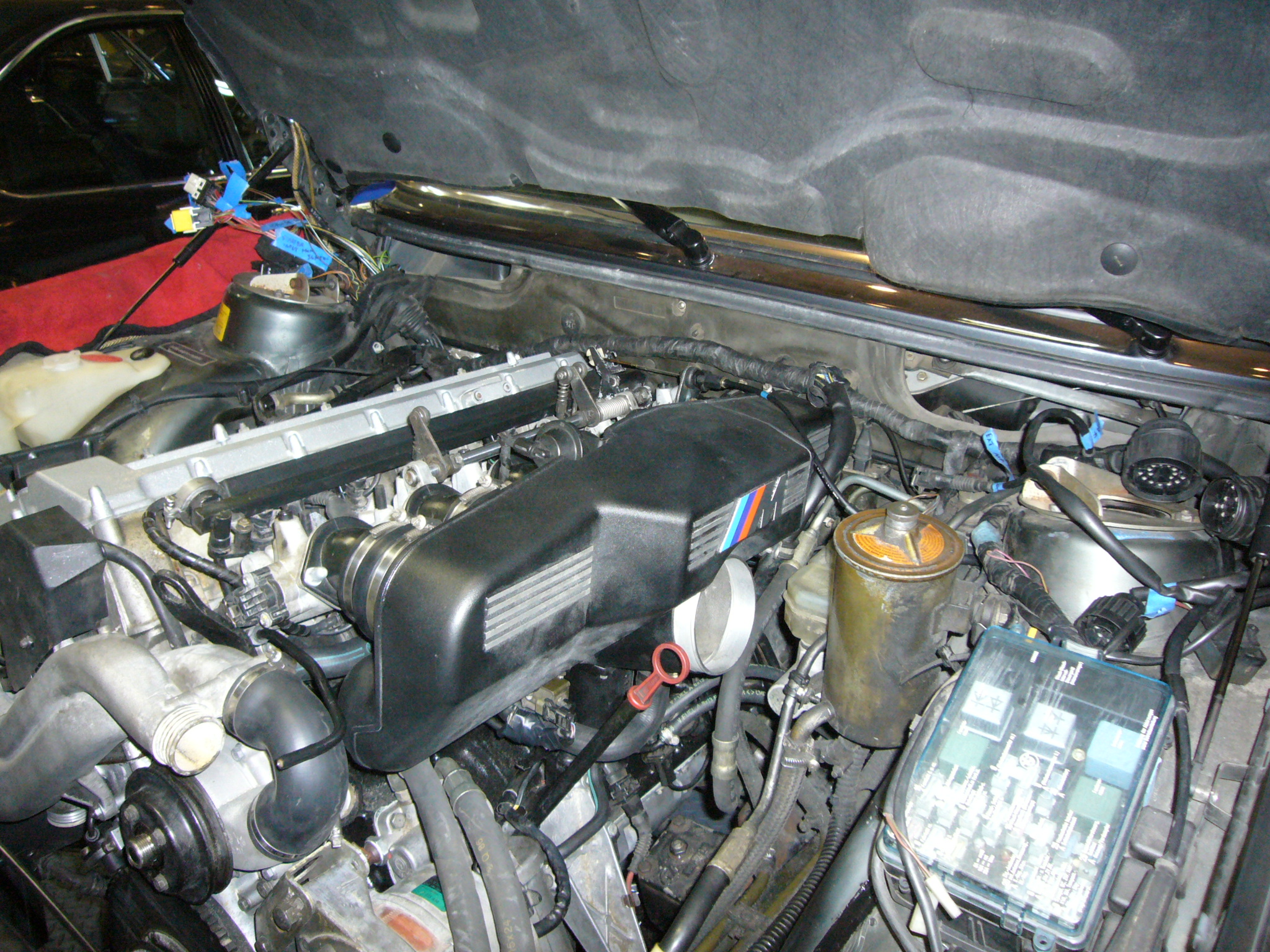
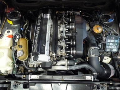
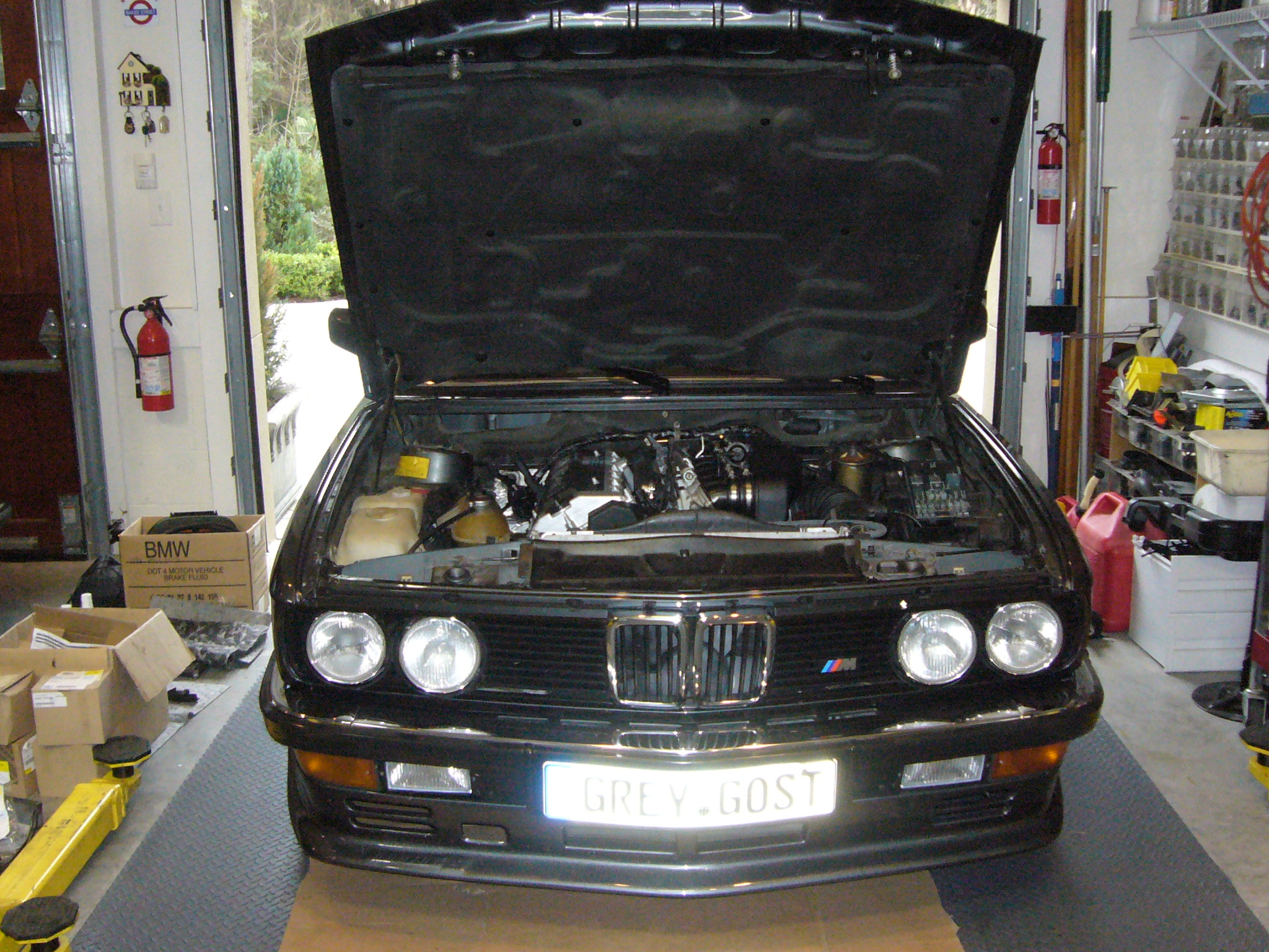
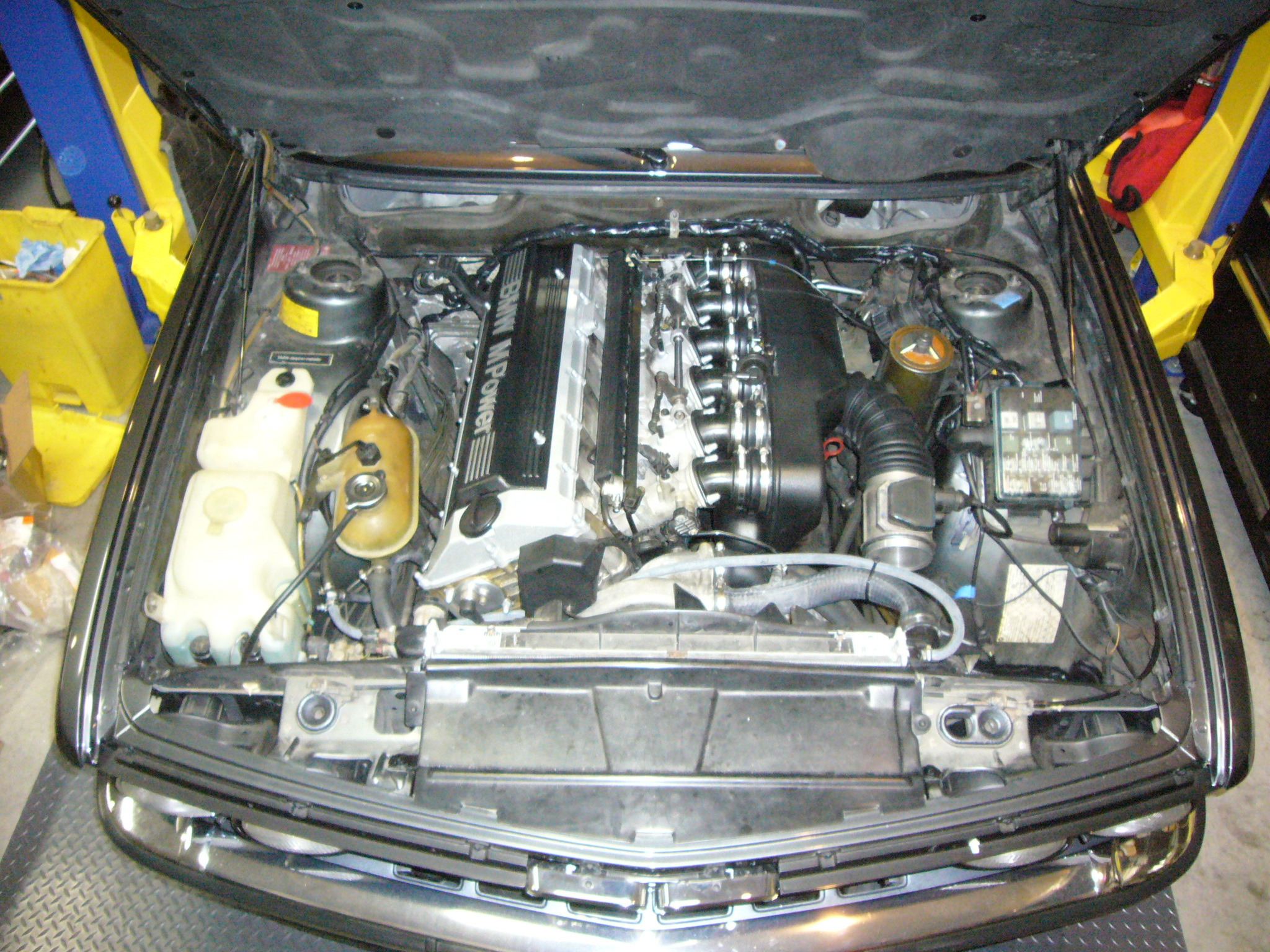
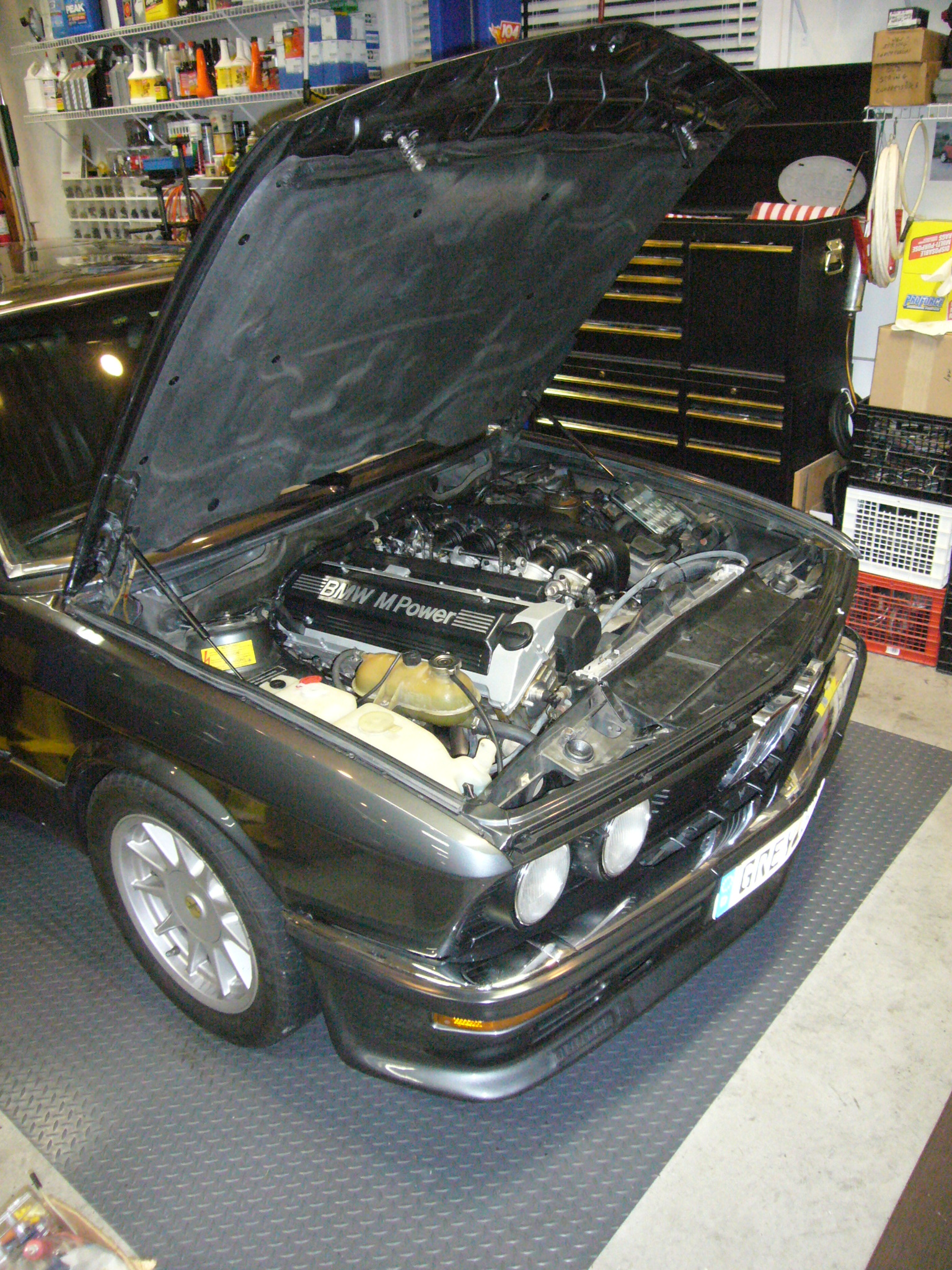
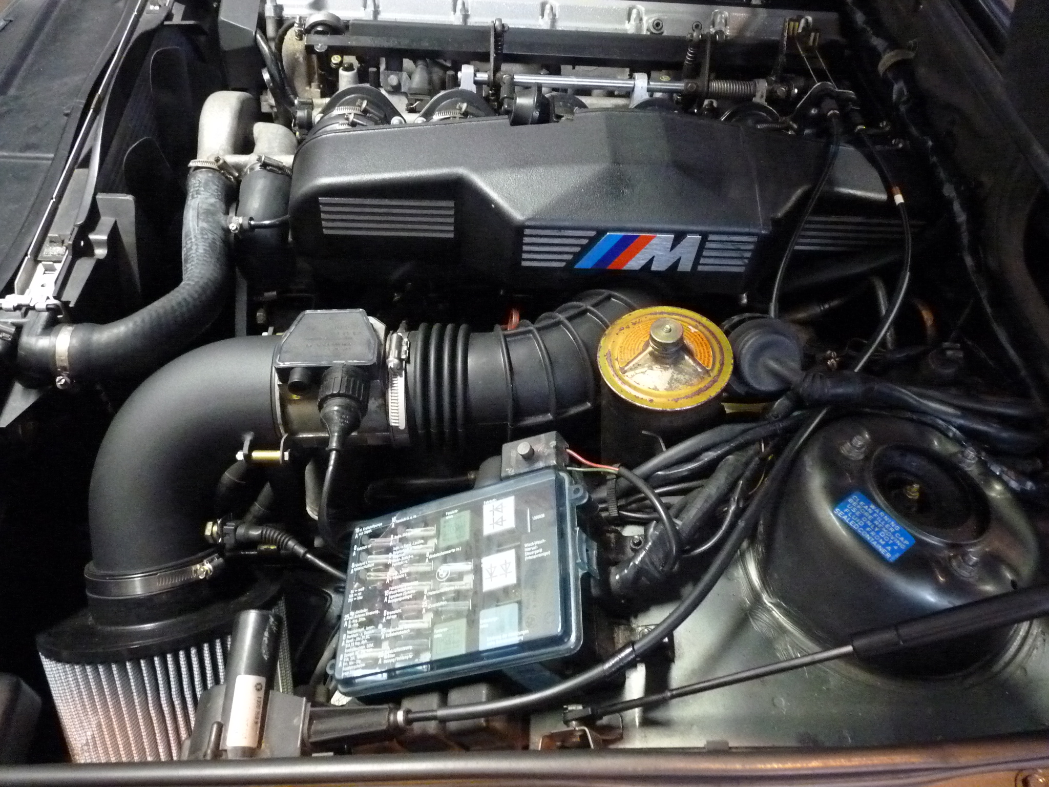
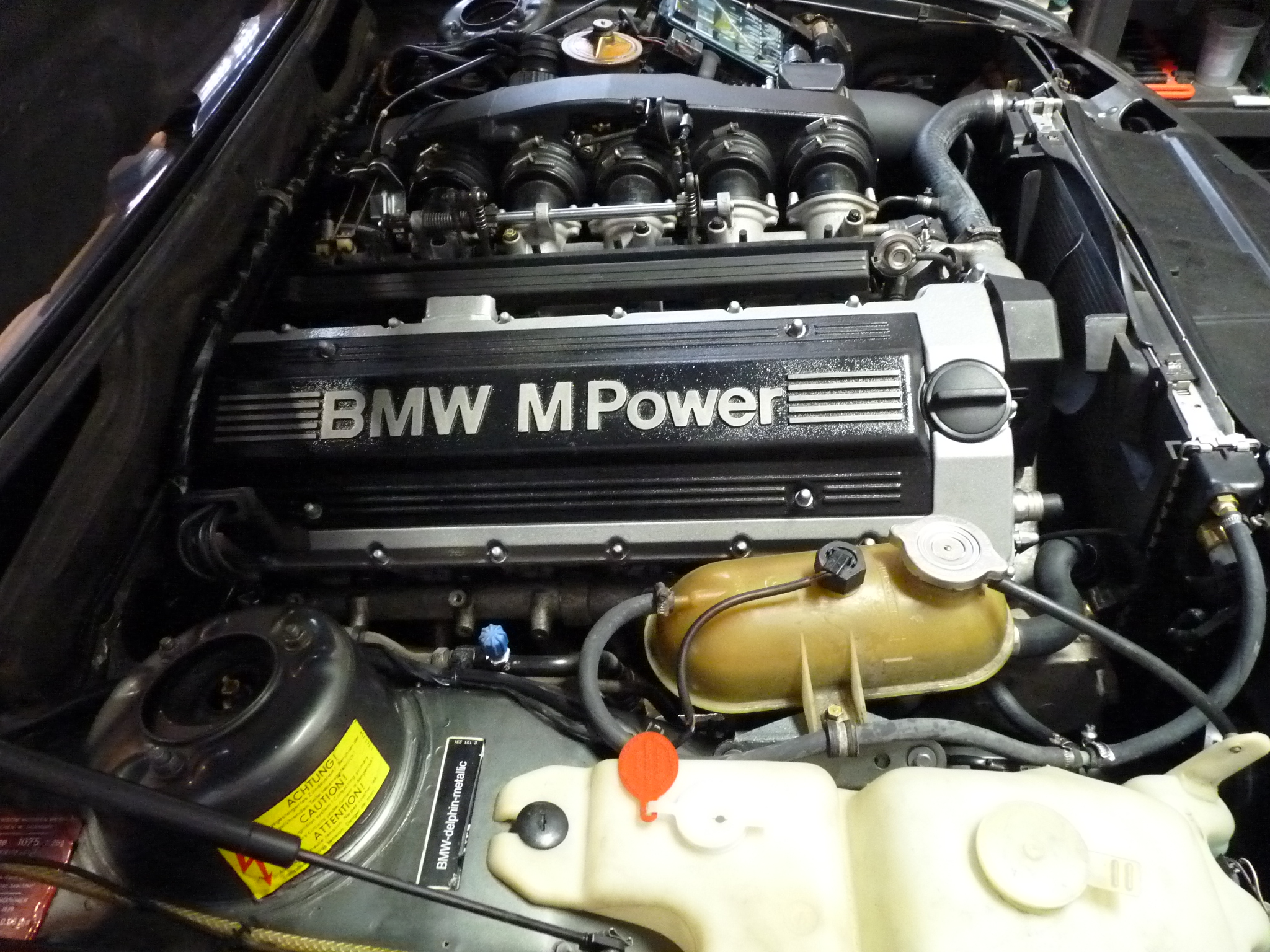
And now we have the final product.
Our second start ever of the motor was captured on video (start in the garage, then slowly backing out outside)
Link to Blackberry Video
There is still a lot of work remaining. We have built a custom exhaust for the car, that will need to be installed and the headers will need to be modified. An alternative is to purchase the Euro M5 exhaust system and install it - however you will sacrifice some top end power because that system can, at best, flow around 300-320 bhp (stock euro motor making 286 bhp), out of the twin 2.0 inch system. The 3.8 will be a little bit strangled. Ideally you'd want to bump up to at least a twin 2.25 inch system, of similar design to the stock US M5 (i.e. X-pipe, cat, resonator, and muffler).
Now all we have to do is drive the requisite 1200 miles for break in, change the oil, and enjoy!
 |
 |
 |
 |
 |
 |
 |
 |
 |
The following pictures are after the A/C was recharged, the custom AC line installed, and the intake completed. The only thing remaining to do is continue the break in and fabricate and install the custom exhaust (including the header collectors and from the headers back) and finalizing the AC wiring.
 |
 |
 |